
Mechanics of Materials (10th Edition)
10th Edition
ISBN: 9780134319650
Author: Russell C. Hibbeler
Publisher: PEARSON
expand_more
expand_more
format_list_bulleted
Concept explainers
Videos
Textbook Question
Chapter 9.3, Problem 9.43P
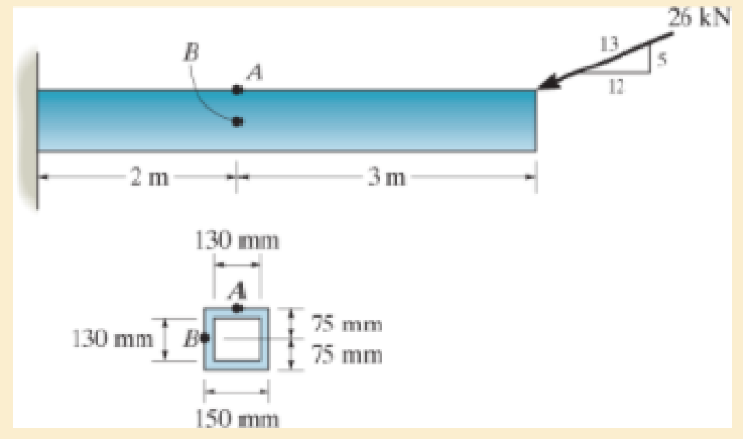
Solve Prob.9–42 for point B.
9–42. The box beam is subjected to the 26-kN force that is applied at the center of its width, 75 mm from each side. Determine the principal stresses at point A and show the results in an element located at this point. Use the shear formula to calculate the shear stress.
Expert Solution & Answer
Want to see the full answer?
Check out a sample textbook solution
Students have asked these similar questions
A short brass cyclinder (denisty=8530 kg/m^3, cp=0.389 kJ/kgK, k=110 W/mK, and alpha=3.39*10^-5 m^2/s) of diameter 4 cm and height 20 cm is initially at uniform temperature of 150 degrees C. The cylinder is now placed in atmospheric air at 20 degrees C, where heat transfer takes place by convection with a heat transfer coefficent of 40 W/m^2K. Calculate (a) the center temp of the cylinder, (b) the center temp of the top surface of the cylinder, and (c) the total heat transfer from the cylinder 15 min after the start of the cooling. Solve this problem using the analytical one term approximation method. (Answer: (a) 45.7C, (b)45.3C, (c)87.2 kJ)
A short brass cyclinder (denisty=8530 kg/m^3, cp=0.389 kJ/kgK, k=110 W/mK, and alpha=3.39*10^-5 m^2/s) of diameter 4 cm and height 20 cm is initially at uniform temperature of 150 degrees C. The cylinder is now placed in atmospheric air at 20 degrees C, where heat transfer takes place by convection with a heat transfer coefficent of 40 W/m^2K. Calculate (a) the center temp of the cylinder, (b) the center temp of the top surface of the cylinder, and (c) the total heat transfer from the cylinder 15 min after the start of the cooling. Solve this problem using the analytical one term approximation method.
A 6 cm high rectangular ice block (k=2.22 W/mK, and alpha=0.124*10^-7 m^2/s) initially at -18 degrees C is placed on a table on its square base 4 cm by 4cm in size in a room at 18 degrees C. The heat transfer coefficent on the exposed surfaces of the ice block is 12 W/m^2K. Disregarding any heat transfer from the base to the table, determine how long it will be before the ice block starts melting. Where on the ice block will the first liquid droplets appear? Solve this problem using the analytical one-term approximation method.
Chapter 9 Solutions
Mechanics of Materials (10th Edition)
Ch. 9.3 - In each case, the state of stress x, y, xy...Ch. 9.3 - Given the state of stress shown on the element,...Ch. 9.3 - Determine the normal stress and shear stress...Ch. 9.3 - Determine the equivalent state of stress on an...Ch. 9.3 - Also, find the corresponding orientation of the...Ch. 9.3 - Determine the equivalent state of stress on an...Ch. 9.3 - Determine the maximum principal stress at point B.Ch. 9.3 - Determine the principal stress at point C.Ch. 9.3 - Prove that the sum of the normal stresses x + y =...Ch. 9.3 - Determine the stress components acting on the...
Ch. 9.3 - Determine the stress components acting on the...Ch. 9.3 - Determine the normal stress and shear stress...Ch. 9.3 - Determine the normal stress and shear stress...Ch. 9.3 - Determine the stress components acting on the...Ch. 9.3 - Determine the stress components acting on the...Ch. 9.3 - Solve Prob.97 using the stress transformation...Ch. 9.3 - Determine the stress components acting on the...Ch. 9.3 - Solve Prob.99 using the stress transformation...Ch. 9.3 - Determine the equivalent state of stress on an...Ch. 9.3 - Determine the equivalent slate of stress on an...Ch. 9.3 - Determine the stress components acting on the...Ch. 9.3 - Determine (a) the principal stresses and (b) the...Ch. 9.3 - The state of stress at a point is shown on the...Ch. 9.3 - Determine the equivalent state of stress on an...Ch. 9.3 - Determine the equivalent state of stress on an...Ch. 9.3 - A point on a thin plate is subjected to the two...Ch. 9.3 - Determine the equivalent state of stress on an...Ch. 9.3 - The stress along two planes at a point is...Ch. 9.3 - The stress acting on two planes at a point is...Ch. 9.3 - The state of stress at a point in a member is...Ch. 9.3 - The grains of wood in the board make an angle of...Ch. 9.3 - The wood beam is subjected to a load of 12 kN. If...Ch. 9.3 - The internal loadings at a section of the beam are...Ch. 9.3 - Solve Prob.925 for point B. 925. The internal...Ch. 9.3 - Solve Prob.925 for point C. 925. The internal...Ch. 9.3 - It is subjected to a torque of 12 kip in. and a...Ch. 9.3 - The bell crank is pinned at A and supported by a...Ch. 9.3 - The beam has a rectangular cross section and is...Ch. 9.3 - A paper tube is formed by rolling a cardboard...Ch. 9.3 - Solve Prob.931 for the normal stress acting...Ch. 9.3 - The 2-in.-diameter drive shaft AB on the...Ch. 9.3 - Determine the principal stresses in the...Ch. 9.3 - The internal loadings at a cross section through...Ch. 9.3 - The internal loadings at a cross section through...Ch. 9.3 - The shaft has a diameter d and is subjected to the...Ch. 9.3 - The steel pipe has an inner diameter of 2.75 in....Ch. 9.3 - Solve Prob.938 for point B, w1ich is located on...Ch. 9.3 - The wide-flange beam is subjected to the 50-kN...Ch. 9.3 - Solve Pro b. 9-40 for point B located on the web...Ch. 9.3 - The box beam is subjected to the 26-kN force that...Ch. 9.3 - Solve Prob.942 for point B. 942. The box beam is...Ch. 9.4 - Use Mohrs circle to determine the normal stress...Ch. 9.4 - Also, find the corresponding orientation of the...Ch. 9.4 - Draw Mohrs circle and determine the principal...Ch. 9.4 - Determine the principal stresses at a point on the...Ch. 9.4 - Determine the principal stresses at point A on the...Ch. 9.4 - Point A is just below the flange.Ch. 9.4 - Solve Prob.9-2 using Mohrs circle. 92. Determine...Ch. 9.4 - Solve Prob.93 using Mohrs circle. 93. Determine...Ch. 9.4 - Solve Prob.96 using Mohrs circle. 96. Determine...Ch. 9.4 - Solve Prob.911 using Mohrs circle. 911. Determine...Ch. 9.4 - Solve Prob.915 using Mohrs circle. 915. The state...Ch. 9.4 - Solve Prob.916 using Mohrs circle. 916. Determine...Ch. 9.4 - Mohrs circle for the state of stress is shown in...Ch. 9.4 - Determine (a) the principal stresses and (b) the...Ch. 9.4 - Determine (a) the principal stresses and (b) the...Ch. 9.4 - Determine the equivalent state of stress if an...Ch. 9.4 - Draw Mohrs circle that describes each of the...Ch. 9.4 - Draw Mohrs circle trial describes each of the...Ch. 9.4 - Determine (a) the principal stresses and (b) the...Ch. 9.4 - Determine (a) the principal stresses and (b) the...Ch. 9.4 - Determine (a) the principal stresses and (b) the...Ch. 9.4 - Determine (a) the principal stresses and (b) the...Ch. 9.4 - Determine (a) the principal stresses and (b) the...Ch. 9.4 - Draw Mohrs circle that describes each of the...Ch. 9.4 - The grains of wood in the board make an angle of...Ch. 9.4 - The post is fixed supported at its base and a...Ch. 9.4 - Determine the principal stresses, the maximum...Ch. 9.4 - The thin-walled pipe has an inner diameter of 0.5...Ch. 9.4 - The frame supports the triangular distributed load...Ch. 9.4 - The frame supports the triangular distributed load...Ch. 9.4 - The rotor shaft of the helicopter is subjected to...Ch. 9.4 - The pedal crank for a bicycle has the cross...Ch. 9.4 - A spherical pressure vessel has an inner radius of...Ch. 9.4 - The cylindrical pressure vessel has an inner...Ch. 9.4 - Determine the normal and shear stresses at point D...Ch. 9.4 - Determine the principal stress at point D, Which...Ch. 9.4 - If the box wrench is subjected to the 50 lb force,...Ch. 9.4 - If the box wrench is subjected to the 50-lb force,...Ch. 9.4 - The post is fixed supported at its base and the...Ch. 9.5 - Draw the three Mohrs circles that describe each of...Ch. 9.5 - Draw the three Mohrs circles that describe the...Ch. 9.5 - Draw the three Mohrs circles that describe the...Ch. 9.5 - Determine the principal stresses and the absolute...Ch. 9.5 - Determine the principal stresses and the absolute...Ch. 9.5 - Determine the principal stresses and the absolute...Ch. 9.5 - Determine the principal stresses and the absolute...Ch. 9.5 - The solid shaft is subjected to a torque, bending...Ch. 9.5 - The frame is subjected to a horizontal force and...Ch. 9.5 - The bolt is fixed to its support at C. If a force...Ch. 9.5 - The bolt is fixed to its support at C. If a force...Ch. 9 - Prob. 9.1RPCh. 9 - The steel pipe has an inner diameter of 2.75 in....Ch. 9 - Determine the equivalent state of stress If an...Ch. 9 - The crane is used to support the 350-lb load....Ch. 9 - Determine the equivalent state of stress on an...Ch. 9 - The propeller shaft of the tugboat is subjected to...Ch. 9 - Determine the principal stresses in the box beam...Ch. 9 - Determine (a) the principal stresses and (b) the...Ch. 9 - Determine the stress components acting on the...
Knowledge Booster


Learn more about
Need a deep-dive on the concept behind this application? Look no further. Learn more about this topic, mechanical-engineering and related others by exploring similar questions and additional content below.Similar questions
- Consider a piece of steel undergoing a decarburization process at 925 degrees C. the mass diffusivity of carbon in steel at 925 degrees C is 1*10^-7 cm^2/s. Determine the depth below the surface of the steel at which the concentration of carbon is reduced to 40 percent from its initial value as a result of the decarburization process for (a) an hour and (b) 10 hours. Assume the concnetration of carbon at the surface is zero throughout the decarburization process.arrow_forwardPlease do not rely too much on chatgpt, because its answer may be wrong. Please consider it carefully and give your own answer. You can borrow ideas from gpt, but please do not believe its answer.Very very grateful! Please do not copy other's work,i will be very very grateful!!arrow_forwardMultiple Choice Circle the best answer to each statement. 1. Which geometry attribute deviation(s) can be limited with a profile of a surface tolerance? A. Location B. Orientation C. Form D. All of the above 2. A true profile may be defined with: A. Basic radii B. Basic angles C. Formulas D. All of the above 3. Which modifier may be applied to the profile tolerance value? A B C. D. All of the above 4. The default tolerance zone for a profile tolerance is: A. Non-uniform B. Unilateral C. Bilateral equal distribution D. Bilateral-unequal distribution 5. An advantage of using a profile tolerance in place of a coordinate tolerance is: A. A bonus tolerance is permitted. B. A datum feature sequence may be specified C. A profile tolerance always controls size D. All of the above 6. The shape of the tolerance zone for a profile tolerance is: A. Two parallel planes B. The same as the true profile of the toleranced surface C. Equal bilateral D. Cylindrical when the diameter symbol is speci- fied…arrow_forward
- One thousand kg/h of a (50-50 wt%) acetone-in-water solution is to be extracted at 25C in a continuous, countercurrent system with pure 1,1,2-trichloroethane to obtain a raffinate containing 10 wt% acetone. Using the following equilibrium data, determine with an equilateral-triangle diagram: a- the minimum flow rate of solvent; b- the number of stages required for a solvent rate equal to 1.5 times minimum, and composition of each streamleaving each stage. c- Repeat the calculation of (a) and (b) if the solvent used has purity 93wt% (4wr% acetone, 3wt% water impurities) acetone water 1,1,2-trichloroethane Raffinate. Weight Extract. Weight 0.6 0.13 0.27 Fraction Acetone Fraction Acetone 0.5 0.04 0.46 0.44 0.56 0.4 0.03 0.57 0.29 0.40 0.3 0.02 0.68 0.12 0.18 0.2 0.015 0.785 0.0 0.0 0.1 0.01 0.89 0.55 0.35 0.1 0.5 0.43 0.07 0.4 0.57 0.03 0.3 0.68 0.02 0.2 0.79 0.01 0.1 0.895 0.005arrow_forward2500 kg/hr of (20-80) nicotine water solution is to be extracted with benzene containing 0.5% nicotine in the 1st and 2ed stages while the 3rd stage is free of nicotine. Cross- current operation is used with different amounts of solvent for each stages 2000kg/hr in the 1st stage, 2300 kg/hr in the 2nd stage, 2600 kg/hr in the 3rd, determine: - a- The final raffinate concentration and % extraction. b- b- The minimum amount of solvent required for counter-current operation if the minimum concentration will be reduced to 5% in the outlet raffinate. Equilibrium data Wt % Nicotine in water Wt % Nicotine in benzene 0 4 16 25 0 4 21 30arrow_forwardQuiz/An eccentrically loaded bracket is welded to the support as shown in Figure below. The load is static. The weld size for weld w1 is h1=6mm, for w2 h2 5mm, and for w3 is h3 -5.5 mm. Determine the safety factor (S.f) for the welds. F=22 kN. Use an AWS Electrode type (E90xx). 140 101.15 REDMI NOTE 8 PRO AI QUAD CAMERA Farrow_forward
- (read image)arrow_forwardProblem 3.30 A piston-cylinder device contains 0.85 kg of refrigerant- 134a at -10°C. The piston that is free to move has a mass of 12 kg and a diameter of 25 cm. The local atmospheric pressure is 100 kPa. Now, heat is transferred to refrigerant-134a until the temperature is 15°C. Determine (a) the final pressure, (b) the change in the volume of the refrigerant, and (c) the change in the enthalpy of the refrigerant-134a. please show Al work step by steparrow_forwardPart 1 The storage tank contains lubricating oil of specific gravity 0.86 In one inclined side of the tank, there is a 0.48 m diameter circular inspection door, mounted on a horizontal shaft along the centre line of the gate. The oil level in the tank rests 8.8 m above the mounted shaft. (Please refer table 01 for relevant SG, D and h values). Describe the hydrostatic force and centre of pressure with the aid of a free body diagram of the inspection door. Calculate the magnitude of the hydrostatic force and locate the centre of pressure. 45° Estimate the moment that would have to be applied to the shaft to open the gate. Stop B If the oil level raised by 2 m from the current level, calculate the new moment required to open the gate. Figure 01arrow_forward
- From thermodynamics please fill in the table show all work step by steparrow_forwardThe 150-lb skater passes point A with a speed of 6 ft/s. (Figure 1) Determine his speed when he reaches point B. Neglect friction. Determine the normal force exerted on him by the track at this point. 25 ft B = 4x A 20 ft xarrow_forwardA virtual experiment is designed to determine the effect of friction on the timing and speed of packages being delivered to a conveyor belt and the normal force applied to the tube. A package is held and then let go at the edge of a circular shaped tube of radius R = 5m. The particle at the bottom will transfer to the conveyor belt, as shown below. Run the simulations for μ = 0, 0.1, 0.2, 0.3, 0.4, 0.5, 0.6 and determine the time and speed at which the package is delivered to the conveyor belt. In addition, determine the maximum normal force and its location along the path as measured by angle 0. Submit in hardcopy form: (0) Free Body Diagram, equations underneath, derivations (a) Your MATLAB mfile (b) A table listing the values in 5 columns: μ, T (time of transfer), V (speed of transfer), 0 (angle of max N), Nmax (max N) (c) Based on your results, explain in one sentence what you think will happen to the package if the friction is increased even further, e.g. μ = 0.8. NOTE: The ODE is…arrow_forward
arrow_back_ios
SEE MORE QUESTIONS
arrow_forward_ios
Recommended textbooks for you
 Elements Of ElectromagneticsMechanical EngineeringISBN:9780190698614Author:Sadiku, Matthew N. O.Publisher:Oxford University Press
 Mechanics of Materials (10th Edition)Mechanical EngineeringISBN:9780134319650Author:Russell C. HibbelerPublisher:PEARSON
 Thermodynamics: An Engineering ApproachMechanical EngineeringISBN:9781259822674Author:Yunus A. Cengel Dr., Michael A. BolesPublisher:McGraw-Hill Education
 Control Systems EngineeringMechanical EngineeringISBN:9781118170519Author:Norman S. NisePublisher:WILEY
 Mechanics of Materials (MindTap Course List)Mechanical EngineeringISBN:9781337093347Author:Barry J. Goodno, James M. GerePublisher:Cengage Learning
 Engineering Mechanics: StaticsMechanical EngineeringISBN:9781118807330Author:James L. Meriam, L. G. Kraige, J. N. BoltonPublisher:WILEY
Elements Of Electromagnetics
Mechanical Engineering
ISBN:9780190698614
Author:Sadiku, Matthew N. O.
Publisher:Oxford University Press
Mechanics of Materials (10th Edition)
Mechanical Engineering
ISBN:9780134319650
Author:Russell C. Hibbeler
Publisher:PEARSON
Thermodynamics: An Engineering Approach
Mechanical Engineering
ISBN:9781259822674
Author:Yunus A. Cengel Dr., Michael A. Boles
Publisher:McGraw-Hill Education
Control Systems Engineering
Mechanical Engineering
ISBN:9781118170519
Author:Norman S. Nise
Publisher:WILEY
Mechanics of Materials (MindTap Course List)
Mechanical Engineering
ISBN:9781337093347
Author:Barry J. Goodno, James M. Gere
Publisher:Cengage Learning
Engineering Mechanics: Statics
Mechanical Engineering
ISBN:9781118807330
Author:James L. Meriam, L. G. Kraige, J. N. Bolton
Publisher:WILEY
Understanding Stress Transformation and Mohr's Circle; Author: The Efficient Engineer;https://www.youtube.com/watch?v=_DH3546mSCM;License: Standard youtube license