
Concept explainers
With regard to the circuit presented in Fig. 9.42, (a) obtain an expression for v(t) which is valid for all t > 0; (b) calculate the maximum inductor current and identify the time at which it occurs; (c) determine the settling time.
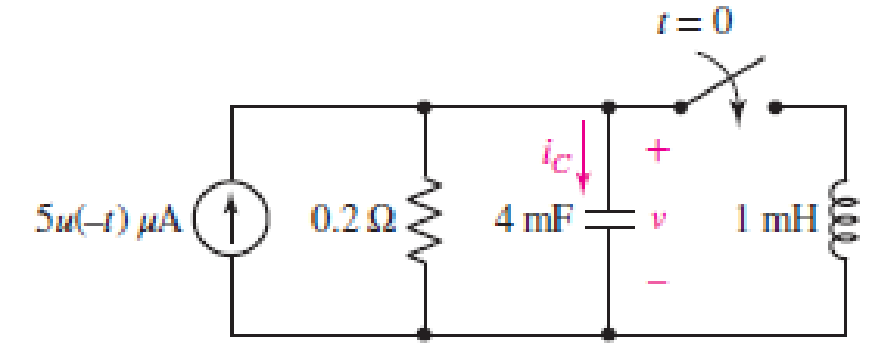
FIGURE 9.42
(a)
Find the equation for voltage
Answer to Problem 16E
The equation of voltage is
Explanation of Solution
Formula used:
The expression for the exponential damping coefficient is as follows:
Here,
The expression for the resonating frequency is as follows:
Here,
The expression for the two solutions of the characteristic equation of a parallel
Here,
Here,
Calculation:
The redrawn circuit is shown in Figure 1 as follows:
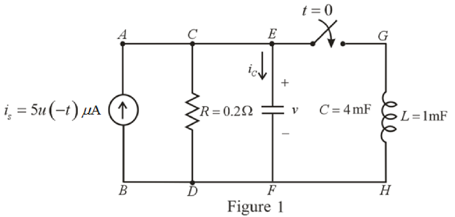
Refer to the Figure 1,
At
The current across inductor is zero because inductor is not energized.
The expression for voltage
Here,
The redrawn circuit at
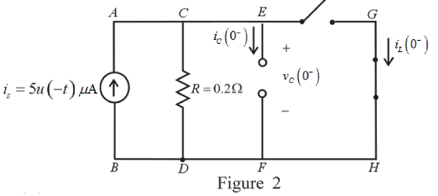
Refer to the Figure 2:
The expression for the voltage across capacitor at
Substitute
The expression for the natural response of voltage for capacitor in the parallel
Substitute
Rearrange for
At
Therefore,
So,
The redrawn circuit is shown in Figure 3 as follows:
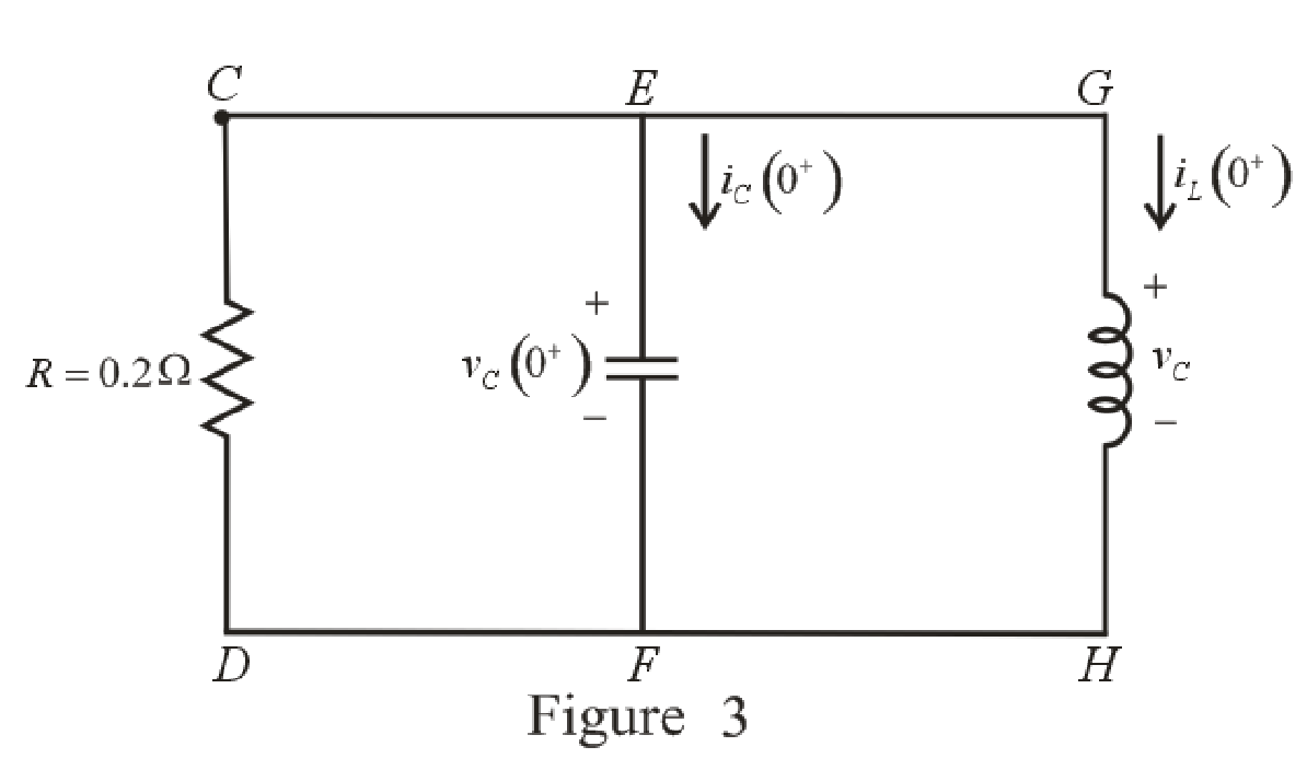
Refer to the Figure 3:
The current across resistor
The expression for KCL at node
Here,
Substitute
The expression for current flowing through capacitor for
Here,
At
The circuit diagram is redrawn as shown in Figure 4 for
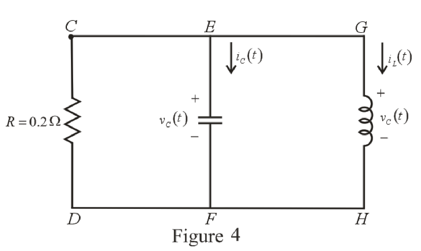
Refer to the redrawn Figure 4:
Substitute
Substitute
As value of exponential frequency
Substitute
Substitute
Differentiate equation (6) both the sides with respect to time
Substitute
Substitute
Substitute
Rearrange for
Rearrange for
Substitute
Substitute
Therefore, voltage across inductor
Conclusion:
Thus, the voltage
(b)
Find the maximum inductor current and the time of occurrence.
Answer to Problem 16E
The maximum inductor current
Explanation of Solution
Calculation:
Refer to the Figure 4:
The expression for inductor current is:
Substitute
For the maximum positive value of inductor current, take the derivative of its equation and then, equate it to zero to find the time at which maximum value of current occurs.
Differentiate equation (14) both the sides with respect to time
Equate the equation to zero.
Rearrange the equation.
Take log both the sides.
Rearrange for
Substitute
This is the maximum inductor current.
Conclusion:
Thus, the maximum inductor current is
(c)
Find the settling time.
Answer to Problem 16E
The settling time of the voltage
Explanation of Solution
Calculation:
The settling time is the time at which inductor current reaches to
Substitute
The settling time is the time at which the inductor current is decreased to
Equation (17) is solved by scientific calculator which can determine the value of time
Conclusion:
Thus, the settling time of the inductor current
Want to see more full solutions like this?
Chapter 9 Solutions
Loose Leaf for Engineering Circuit Analysis Format: Loose-leaf
- (A) Consider a communication system where the number of successful transsions out of 10 trials follows a binomial distribution. The success probability for each triat is 0,95, Let X be the random variable representing the number of successful transmissions. -Sketch the cumulative distribution function (CDF) of the distribution. 2- Find Skewness coefficients and check if the distribution is symmetrical or skewed to the right or left. 3- Find kurtosis coefficients, Check if the distribution is mesokurtic, leptokurtic or platykurtic. 4- Find the probability of getting at most eigh. successful transmissions. 5- Find the probability P(20 with a mean 2-1 calculate the probability that the noise is greater than 3 units.arrow_forwardQ4: (A) Find the mean of a random variable X if S f(x)= 2x 0 2 for 0arrow_forward(A) Suopces the current measurements in a strip of wire are normally distributed with ca-10(mA) and a varieocom (mA)² 1- What is the probability that a current measurement lies between 7.4 and 11.6 mA? 2-Drew the probability density function of the current distribution. (8) A factory produces light bulbs with a koown probability of P(D)-0.08 that & bulo is dalective. If a bulb is defective, the probability that the quality control test detects it is defective is P(TID)-0.90. Conversely, if a bulb is not defective, the probability that the test Telesly indicaton k as defective is P(TID)-0.05. calculate the probability that a light b is notually defective given that the test result is positive, F(DIT).arrow_forwardTitle: Modelling and Simulating Boost Converter Battery Charging Powered by PV Solar Question: I need a MATLAB/Simulink model for a Boost Converter used to charge a battery, powered by a PV solar panel. The model should include: 1. A PV solar panel as the input power source. 2. A Boost Converter circuit for voltage regulation. 3. A battery charging system. 4. Simulation results showing voltage, current, and efficiency of the system. Please provide the Simulink file and any necessary explanations.arrow_forwardPlease answerarrow_forwardPlease solvearrow_forwardarrow_back_iosSEE MORE QUESTIONSarrow_forward_ios
 Introductory Circuit Analysis (13th Edition)Electrical EngineeringISBN:9780133923605Author:Robert L. BoylestadPublisher:PEARSON
 Delmar's Standard Textbook Of ElectricityElectrical EngineeringISBN:9781337900348Author:Stephen L. HermanPublisher:Cengage Learning
 Programmable Logic ControllersElectrical EngineeringISBN:9780073373843Author:Frank D. PetruzellaPublisher:McGraw-Hill Education
 Fundamentals of Electric CircuitsElectrical EngineeringISBN:9780078028229Author:Charles K Alexander, Matthew SadikuPublisher:McGraw-Hill Education
 Electric Circuits. (11th Edition)Electrical EngineeringISBN:9780134746968Author:James W. Nilsson, Susan RiedelPublisher:PEARSON
 Engineering ElectromagneticsElectrical EngineeringISBN:9780078028151Author:Hayt, William H. (william Hart), Jr, BUCK, John A.Publisher:Mcgraw-hill Education,


