
Videos
Consider the circuit depicted in Fig. 9.40. (a) Obtain an expression for iL(t) valid for all t > 0. (b) Obtain an expression for iR(t) valid for all t > 0. (c) Determine the settling time for both iL and iR.
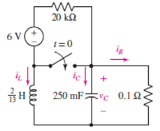
■ FIGURE 9.40
(a)
Obtain an expression for
Answer to Problem 13E
The current across inductor
Explanation of Solution
Formula used:
The expression for the exponential damping coefficient in parallel
Here,
The expression for the resonating frequency in parallel
Here,
The expression for the two solutions of the characteristic equation of a parallel
Here,
The expression for the natural response of the parallel
Here,
Calculation:
The redrawn circuit is shown in Figure 1 as follows:
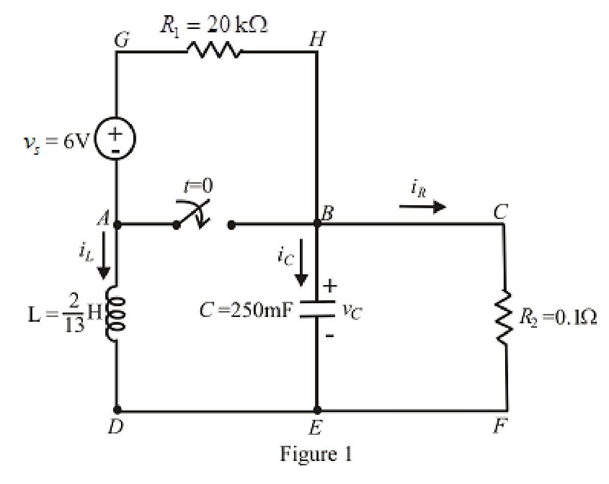
Refer to the Figure 1:
At
Here,
The redrawn circuit at
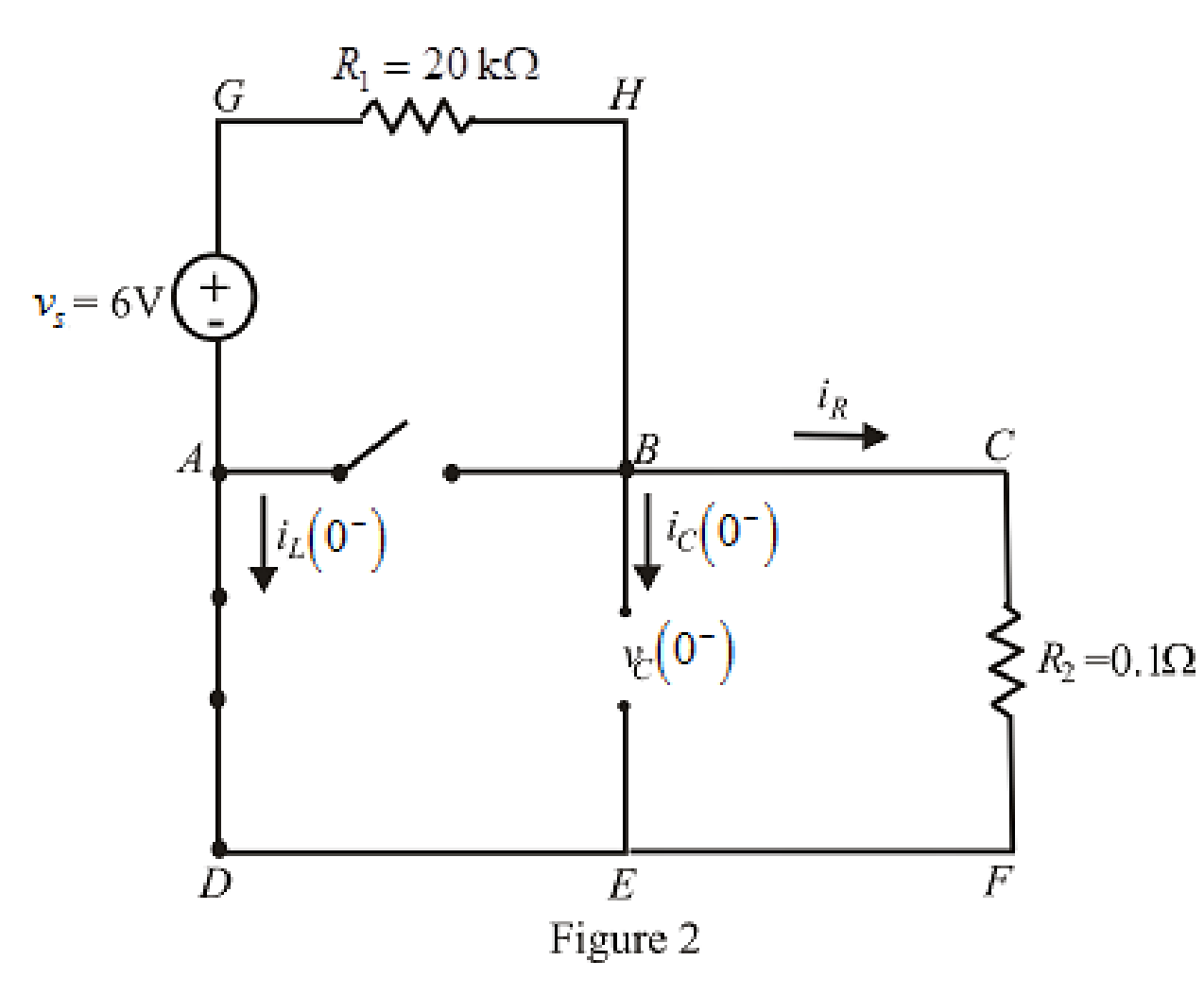
Refer to the Figure 2:
Substitute
The expression for voltage
Here,
Substitute
Substitute
Rearrange for
At
The voltage across inductor is same as voltage across capacitor due to parallel circuit and thus, the expression for voltage across inductor is:
The redrawn circuit is shown in Figure 3 as follows:
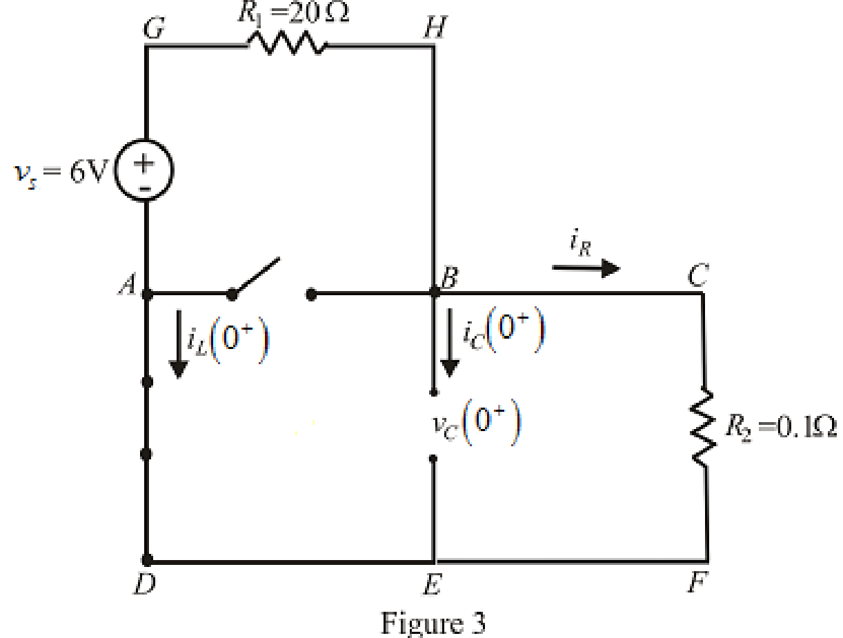
Refer to the Figure 3:
Substitute
Substitute
Differentiate equation (5) both the sides with respect to time
The expression for the voltage across inductor at time
At
Substitute
Rearrange for
Substitute
At
The circuit diagram is redrawn as shown in Figure 4 for
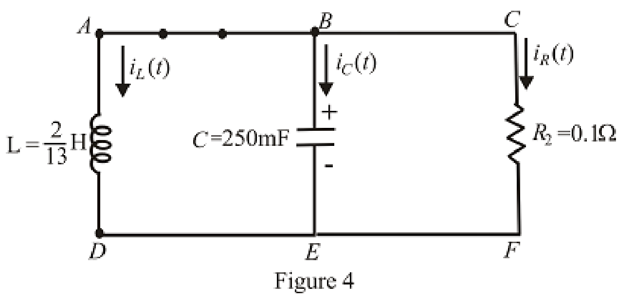
Refer to the redrawn Figure 4:
Substitute
Substitute
As value of exponential frequency
Substitute
Substitute
Substitute
Substitute
Solve for
Rearrange for
Substitute
Rearrange for
Substitute
Conclusion:
Thus, the current across inductor
(b)
Find the equation for current across resistor for
Answer to Problem 13E
The equation of current
Explanation of Solution
Calculation:
Refer to the Figure 3:
The expression for current across resistor at
At
Therefore,
At
Substitute
At
Substitute
Conclusion:
Thus, the equation of current
(c)
Find the settling time for both
Answer to Problem 13E
The settling time for
Explanation of Solution
Calculation:
The settling time is the time at which current reaches to
Since the inductor current is exponential in nature and time cannot be taken as negative, therefore, inductor current takes its maximum value at
Substitute
The maximum value of current is:
The expression for current at settling time
Substitute
The settling time is the time at which the current is decreased to
Equation (24) is solved by scientific calculator which can determine the value of time
Take log both the side in equation (25).
Rearrange for
Substitute
The maximum value of current is:
The expression for current at settling time
Substitute
The settling time is the time at which the current is decreased to
The equation can be approximated for
Take log both the sides of equation (28).
Rearrange for
Conclusion:
Thus, the settling time for
Want to see more full solutions like this?
Chapter 9 Solutions
Loose Leaf for Engineering Circuit Analysis Format: Loose-leaf


- Example2:- 8. = e.A nia +2.1 = Find the maximum steady-state power capability of a system consisting of a generator equivalent reactance of 0.4pu connected to an infinite bus through a series reactance of 1.0 p.u. The terminal voltage of the generator is held at1.10 p.u. and the voltage of the infinite bus is 1.0 p.u.arrow_forwardB) A 60-Hz generator is supplying 60% of P max to an infinite bus through a reactive network. A fault occurs which increases the reactance of the network between the generator internal voltage and the infinite bus by 400%. When the fault is cleared, the maximum power that can be delivered is 80% of the original maximum value. Determine the critical clearing angle for the condition described.arrow_forwardIn the circuit shown, let Vs-9, R₁-8, R2-2, and R3-4. Use Nodal analysis to determine the current lo. In particular find: V2= 10= A The relative tolerance for this problem is 5 %. R₁ V₁ + ww R₂ Vs V₂ 21 x R3arrow_forward
- 1. Choose all nodes that must be included, if any, to construct the supernode for Nodal analysis. OV1, V3 OV1, V2 ○ V2, V3 OV1, V2, V4 OV1, V2, V3 O V2, V3, V4 2. Write KCL equation (Nodal equation) at super-node. Write your expression in terms of node voltages V1, V2, V3 and V4 and of the form (G11 V1+G12 V2+G13 V3+G14 V4 = 11), then enter the corresponding values: At super-node KCL: 1/Q G11 1/0 G12 1/Ω G13 1/Q G14 A 3. Use the above equation, the circuit and and super-node inner expression to calculate V3 and then lo : V3= V 10 = R3 Vst + A V₁ + VS2 V₂ V3 w W R₁ R₂ R4 ww R5 V4 V$3arrow_forwardEnter the matrix values (numerical) to solve for voltages at nodes v1, and v2, for the circuit shown, using Nodal equations. In the matrix, row 1, and row 2, correspond to node v1, and node v2 current expressions, respectively. Let Is1=14, Is2=7, R₁=5, R₂-8, R3=2, and R4-5. [G11 G12] [Vi₁ The matrix values are shown here: = G21 G22 [V2] [41] [12] {Hint: As discussed in class and to avoid sign errors, assume nodal currents are locally defined at each node (leaving) and use node labeling as indicated in the circuit. } The relative tolerance for this problem is 5%. VI R2 ww Isl 12 NODE v1 G11 G12 RI 1/Q 1/0 A 4= NODE v2 G21- 1/Q G22 1/0 12 W A === www R3 R4 www Use Cramer's rule (matrix), substitution, or any other method to calculate the voltages: v1 = V v2= V Is2arrow_forwardOnly expert should attemptarrow_forward
- For the circuit shown below, let l₁ = 9, 1₂ = 14, 13= 12, R₁ = 3, R₂ = 8, and R3 = 5. Use nodal equations to determine V1, V2 and I, as follows: • Consider Node 1, obtain a nodal equation in terms of V₁ and V₂ voltages. Simplify your equation to the format 1V1 + b,V₂ = c, then enter the corresponding values of coefficients b₁ and c₁ 1. b₁ =( C₁ = • Now consider Node 2, obtain a second nodal equation in terms of V₁ and V2 voltages. Simplify your equation to the format -1V₁+b2V2=c2 then enter the corresponding values of coefficients b₂ and c₂ 2. (b₂ = value.) ,၄၇ = - 3. Use (1) and (2) to determine V₂ = 4. Determine V₁ 5. Determine | = i 12 V₁ R1 20 www R2 ww I The relative tolerance for this problem is 5%. R3 This is not a decimal or integer www i3arrow_forwardFor the circuit shown, let V1 = 19 V, Vs2 = 76 V, R₁ = 9, R2 = 9, and R3 = 7. Use Nodal analysis to determine the voltage V2 and the current lo, choose the closet values: V2- 4.788 10 = ○ 2.28 11.978 17.761 35.522 23.957 -9.146 8.32 10.173 A O-7.435 O-5.783 10.531 V sl ་ ་ ་ ན ་་་ ་ ་ ་ ་ ་ ་ ་ ་ +1 ww R₁ R₂ ww R3 Io +1 VS2arrow_forwardNO AI PLEASEarrow_forward
- NO AI PLEASEarrow_forwardProblem 4 Consider the following system. In the figure, y(t) denotes the displacement of the mass and u(t) denotes the force applied to the mass. b1 u(t) y(t) + b2 M 0000 0000 K1 K2 a) Find the differential equation model of the system. b) Find the state-space model for the system. Write x, A, B, C and D clearly in your answer.arrow_forwardNO AI PLEASEarrow_forward
 Introductory Circuit Analysis (13th Edition)Electrical EngineeringISBN:9780133923605Author:Robert L. BoylestadPublisher:PEARSON
 Delmar's Standard Textbook Of ElectricityElectrical EngineeringISBN:9781337900348Author:Stephen L. HermanPublisher:Cengage Learning
 Programmable Logic ControllersElectrical EngineeringISBN:9780073373843Author:Frank D. PetruzellaPublisher:McGraw-Hill Education
 Fundamentals of Electric CircuitsElectrical EngineeringISBN:9780078028229Author:Charles K Alexander, Matthew SadikuPublisher:McGraw-Hill Education
 Electric Circuits. (11th Edition)Electrical EngineeringISBN:9780134746968Author:James W. Nilsson, Susan RiedelPublisher:PEARSON
 Engineering ElectromagneticsElectrical EngineeringISBN:9780078028151Author:Hayt, William H. (william Hart), Jr, BUCK, John A.Publisher:Mcgraw-hill Education,