
Loose Leaf for Engineering Circuit Analysis Format: Loose-leaf
9th Edition
ISBN: 9781259989452
Author: Hayt
Publisher: Mcgraw Hill Publishers
expand_more
expand_more
format_list_bulleted
Concept explainers
Videos
Textbook Question
Chapter 9, Problem 54E
Consider the circuit depicted in Fig. 9.55. If vs(t) = −8 + 2u(t) V, determine (a) vC(0+); (b) iL(0+); (c) vC(∞); (d) vC(t = 150 ms).
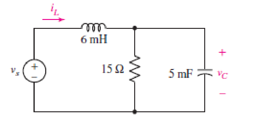
FIGURE 9.55
Expert Solution & Answer
Want to see the full answer?
Check out a sample textbook solution
Students have asked these similar questions
Please draw out the circuits
Q2 but when you get to part 3, can you please draw it out
please solve manually. I need the drawing and the values too. Thank you!
Chapter 9 Solutions
Loose Leaf for Engineering Circuit Analysis Format: Loose-leaf
Ch. 9.1 - A parallel RLC circuit contains a 100 2 resistor...Ch. 9.2 - After being open for a long time, the switch in...Ch. 9.2 - Prob. 3PCh. 9.2 - Prob. 4PCh. 9.3 - (a) Choose R1 in the circuit of Fig. 9.14 so that...Ch. 9.4 - Prob. 6PCh. 9.5 - Prob. 7PCh. 9.5 - Prob. 8PCh. 9.6 - Let is = 10u(t) 20u(t) A in Fig. 9.31. Find (a)...Ch. 9.6 - Let vs = 10 + 20u(t) V in the circuit of Fig....
Ch. 9.7 - Alter the capacitor value and voltage source in...Ch. 9 - For a certain source-free parallel RLC circuit, R...Ch. 9 - Element values of 10 mF and 2 nH are employed in...Ch. 9 - If a parallel RLC circuit is constructed from...Ch. 9 - Prob. 4ECh. 9 - You go to construct the circuit in Exercise 1,...Ch. 9 - A parallel RLC circuit has inductance 2 mH and...Ch. 9 - Prob. 7ECh. 9 - A parallel RLC circuit has R = 1 k, L = 50 mH. and...Ch. 9 - Prob. 9ECh. 9 - Prob. 10ECh. 9 - The current flowing through a 5 resistor in a...Ch. 9 - For the circuit of Fig.9.40, obtain an expression...Ch. 9 - Consider the circuit depicted in Fig. 9.40. (a)...Ch. 9 - With regard to the circuit represented in Fig....Ch. 9 - (a) Assuming the passive sign convention, obtain...Ch. 9 - With regard to the circuit presented in Fig. 9.42,...Ch. 9 - Obtain expressions for the current i(t) and...Ch. 9 - FIGURE 9.43 Replace the 14 resistor in the...Ch. 9 - Design a complete source-free parallel RLC circuit...Ch. 9 - For the circuit represented by Fig. 9.44, the two...Ch. 9 - Prob. 21ECh. 9 - Prob. 22ECh. 9 - A critically damped parallel RLC circuit is...Ch. 9 - A source-free parallel RLC circuit has an initial...Ch. 9 - A critically damped parallel RLC circuit is...Ch. 9 - For the circuit of Fig. 9.45, is(t) = 30u(t) mA....Ch. 9 - Prob. 27ECh. 9 - The circuit of Fig. 9.44 is rebuilt such that the...Ch. 9 - Prob. 29ECh. 9 - Prob. 30ECh. 9 - The source-free circuit depicted in Fig. 9.1 is...Ch. 9 - (a) Graph the current i for the circuit described...Ch. 9 - Analyze the circuit described in Exercise 31 to...Ch. 9 - A source-free parallel RLC circuit has capacitance...Ch. 9 - Prob. 35ECh. 9 - Obtain an expression for vL(t), t 0, for the...Ch. 9 - For the circuit of Fig. 9.47, determine (a) the...Ch. 9 - (a) Design a parallel RLC circuit that provides a...Ch. 9 - The circuit depicted in Fig. 9.48 is just barely...Ch. 9 - When constructing the circuit of Fig. 9.48, you...Ch. 9 - The circuit of Fig. 9.22a is constructed with a...Ch. 9 - Prob. 42ECh. 9 - Prob. 43ECh. 9 - The simple three-element series RLC circuit of...Ch. 9 - Prob. 45ECh. 9 - Prob. 46ECh. 9 - Prob. 47ECh. 9 - With reference to the series RLC circuit of Fig....Ch. 9 - Obtain an expression for i1 as labeled in Fig....Ch. 9 - The circuit in Fig. 9.52 has the switch in...Ch. 9 - For the circuit in Fig. 9.52, determine the value...Ch. 9 - In the series circuit of Fig. 9.53, set R = 1 ....Ch. 9 - Evaluate the derivative of each current and...Ch. 9 - Consider the circuit depicted in Fig. 9.55. If...Ch. 9 - Prob. 55ECh. 9 - In the circuit shown in Fig. 9.56, (a) obtain an...Ch. 9 - Prob. 57ECh. 9 - For the circuit represented in Fig. 9.57, (a)...Ch. 9 - FIGURE 9.57 Replace the 1 resistor in Fig. 9.57...Ch. 9 - A circuit has an inductive load of 2 H, a...Ch. 9 - (a) Adjust the value of the 3 resistor in the...Ch. 9 - Determine expressions for vC(t) and iL(t) in Fig....Ch. 9 - The capacitor in the LC circuit in Fig. 9.60 has...Ch. 9 - Suppose that the switch in the circuit in Fig....Ch. 9 - The capacitor in the circuit of Fig. 9.63 is set...Ch. 9 - The physical behavior of automotive suspension...Ch. 9 - A lossless LC circuit can be used to provide...
Knowledge Booster


Learn more about
Need a deep-dive on the concept behind this application? Look no further. Learn more about this topic, electrical-engineering and related others by exploring similar questions and additional content below.Similar questions
- Two alternators, Y-connected 6.6 kV supply a load of 3000 kW at 0.8 p.f lagging. The synchronous mpedance of first alternator is (0.5+j10) Q/ph and second alternator is (0.4+j12) /ph. First alternator delivers 150 amp at 0.875 lag p.f. The two alterators are shared load equally. Determine the current, p.f., induced e.m.f, load angel, and maximum developed power of each alternator?arrow_forwardA domestic load of 2300 kW at 0.88 p.f lagging and a motors load of 3400 kW at 0.85 p.f lagging are supplied by two alternators operating in parallel. If one alternator is delivering a load of 3300 kW at 0.9 p.f lagging, what will be the output power and p.f of the other alternator?arrow_forwardDetermine the value of Rr that necessary for the circuit in Fig.(2) to operate as an oscillator and then determine the frequency of oscillation. 0.001 F 0.001 F 0.001 F R₁ • 10 ΚΩ R₁ 10 k R • 10 ΚΩarrow_forward
- (a) For the circuit shown in Figure Q3(a) (RFC and Cc are forbias) (i) (ii) Draw the AC small signal equivalent circuit of the oscillator. From this equivalent circuit derive an equation for fo and the gain condition for the oscillations to start. VDD www RG eee RFC H Cc 北 5 C₁ L 000 C₂ Voarrow_forwardPlease solve this question step by step handwritten solution and do not use chat gpt or any ai toolsfor part ii) you may need to use nodal analysisarrow_forward12.1. Find the steady-state response vo (t) for the network. 00000- 1Ω ww 12 cos(t) V + www 202 1 H 202 1 F + 1Ω νο -arrow_forward
- A Three-phase, 12 pole, Y-connected alternator has 108 slots and 14 conductors per slot. The windings are (5/6 th) pitched. The flux per pole is 57 mWb distributed sinusoidally over the pole. If the machine runs at 500 r.p.m., determine the following: (a) The frequency of the generated e.m.f., (b) The distribution factor, (c) The pitch factor, and (d) The phase and line values of the generated e.m.f.?arrow_forwardTwo 3-ph, 6.6 kV, Y-connected, alternators supply a load of 3000 kW at 0.8 p.f. lagging. The synchronou impedance per phase of machine A is (0.5+110) and that of machine B is (0.4 +J12) . The excitation of machine A adjusted so that it delivers 150 A. The load is shared equally between the machines. Determine the armature curre p.f., induced e.m.f., and load angle of each machine?arrow_forwardName the circuit below? The output voltage is initially zero and the pulse width is 200 μs. Find the Vout and draw the output waveform? +2.5 V V 247 -2.5 V C 0.01 F Ri W 10 ΚΩarrow_forward
- Please work outarrow_forwardFind Vfinal when Vs up and Vs V. Which LED will light in each case? Red or Green? Justify your answers. Fill the table below. Vs 8 ΚΩ Vos Χρι + 3 ΚΩ www 6 ΚΩ ww 4 ΚΩ Yo www Vo Vec-12 V Nol V final Vm w 3 ΚΩ 5 V 38 ΚΩ R= 1 kQ V -12 V Red LED Green LED Vs Vo Vfinal Which LED is ON? Varrow_forwardCircuits help please solve and explain. Question in images providedarrow_forward
arrow_back_ios
SEE MORE QUESTIONS
arrow_forward_ios
Recommended textbooks for you
 Introductory Circuit Analysis (13th Edition)Electrical EngineeringISBN:9780133923605Author:Robert L. BoylestadPublisher:PEARSON
 Delmar's Standard Textbook Of ElectricityElectrical EngineeringISBN:9781337900348Author:Stephen L. HermanPublisher:Cengage Learning
 Programmable Logic ControllersElectrical EngineeringISBN:9780073373843Author:Frank D. PetruzellaPublisher:McGraw-Hill Education
 Fundamentals of Electric CircuitsElectrical EngineeringISBN:9780078028229Author:Charles K Alexander, Matthew SadikuPublisher:McGraw-Hill Education
 Electric Circuits. (11th Edition)Electrical EngineeringISBN:9780134746968Author:James W. Nilsson, Susan RiedelPublisher:PEARSON
 Engineering ElectromagneticsElectrical EngineeringISBN:9780078028151Author:Hayt, William H. (william Hart), Jr, BUCK, John A.Publisher:Mcgraw-hill Education,
Introductory Circuit Analysis (13th Edition)
Electrical Engineering
ISBN:9780133923605
Author:Robert L. Boylestad
Publisher:PEARSON
Delmar's Standard Textbook Of Electricity
Electrical Engineering
ISBN:9781337900348
Author:Stephen L. Herman
Publisher:Cengage Learning
Programmable Logic Controllers
Electrical Engineering
ISBN:9780073373843
Author:Frank D. Petruzella
Publisher:McGraw-Hill Education
Fundamentals of Electric Circuits
Electrical Engineering
ISBN:9780078028229
Author:Charles K Alexander, Matthew Sadiku
Publisher:McGraw-Hill Education
Electric Circuits. (11th Edition)
Electrical Engineering
ISBN:9780134746968
Author:James W. Nilsson, Susan Riedel
Publisher:PEARSON
Engineering Electromagnetics
Electrical Engineering
ISBN:9780078028151
Author:Hayt, William H. (william Hart), Jr, BUCK, John A.
Publisher:Mcgraw-hill Education,
ENA 9.2(1)(En)(Alex) Sinusoids & Phasors - Explanation with Example 9.1 ,9.2 & PP 9.2; Author: Electrical Engineering Academy;https://www.youtube.com/watch?v=vX_LLNl-ZpU;License: Standard YouTube License, CC-BY
Electrical Engineering: Ch 10 Alternating Voltages & Phasors (8 of 82) What is a Phasor?; Author: Michel van Biezen;https://www.youtube.com/watch?v=2I1tF3ixNg0;License: Standard Youtube License