Statics and Mechanics of Materials (5th Edition)
5th Edition
ISBN: 9780134382593
Author: Russell C. Hibbeler
Publisher: PEARSON
expand_more
expand_more
format_list_bulleted
Concept explainers
Textbook Question
Chapter 8.6, Problem 22P
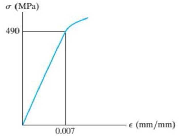
The elastic portion of the stress-strain diagram for an aluminum alloy is shown in the figure. The specimen from which it was obtained has an original diameter of 12.7 mm and a gage length of 50.8 mm. When the applied load on the specimen is 50 kN, the diameter is 12.67494 mm. Determine Poisson’s ratio for the material.

Probs. 8–22/23
Expert Solution & Answer
Want to see the full answer?
Check out a sample textbook solution
Students have asked these similar questions
A 5 cm external diameter, 10 m long hot water pipe at 80 degrees C is losing heat to the surrounding air at 5 degrees C by natural convestion with a heat transfer coefficient of 25 W/m^2 K. Determine the rate of heat loss from the pipe by natural convection.
The outer surface of a spacecraft in space has emissivity of 0.8 and a solar absorptivity of 0.3. If solar radiation in incident on the spacecraft at a rate of 950 W/m^2, determine the surface temp of the spacecraft when the radiation emitted equals the solar energy absorbed.
Of the following pairs of material types, indicate whether any of them satisfy the condition that both elements of the pair are generically related to the property of ductility.(A). Yes, ceramics and polymers.(B). No, none of the pairs.(C). Yes, metals and ceramics.(D). Yes, polymers and metals.
Chapter 8 Solutions
Statics and Mechanics of Materials (5th Edition)
Ch. 8.4 - Define a homogeneous material.Ch. 8.4 - Prob. 2FPCh. 8.4 - Prob. 3FPCh. 8.4 - Prob. 4FPCh. 8.4 - Prob. 5FPCh. 8.4 - As the temperature increases the modulus of...Ch. 8.4 - Prob. 7FPCh. 8.4 - Prob. 8FPCh. 8.4 - Prob. 9FPCh. 8.4 - Prob. 10FP
Ch. 8.4 - The material for the 50-mm-long specimen has the...Ch. 8.4 - If the elongation of wire BC is 0.2 mm after the...Ch. 8.4 - A tension test was performed on a steel specimen...Ch. 8.4 - Data taken from a stressstrain test for a ceramic...Ch. 8.4 - Data taken from a stressstrain test for a ceramic...Ch. 8.4 - Prob. 4PCh. 8.4 - The stress-strain diagram for a steel alloy having...Ch. 8.4 - Prob. 6PCh. 8.4 - The rigid beam is supported by a pin at C and an...Ch. 8.4 - The rigid beam is supported by a pin at C and an...Ch. 8.4 - Prob. 9PCh. 8.4 - The stressstrain diagram for an aluminum alloy...Ch. 8.4 - The stressstrain diagram for an aluminum alloy...Ch. 8.4 - Prob. 12PCh. 8.4 - A bar having a length of 5 in. and cross-sectional...Ch. 8.4 - The rigid pipe is supported by a pin at A and an...Ch. 8.4 - The rigid pipe is supported by a pin at A and an...Ch. 8.4 - Prob. 16PCh. 8.4 - The rigid beam is supported by a pin at C and an...Ch. 8.4 - Prob. 18PCh. 8.4 - Prob. 19PCh. 8.6 - A 100 mm long rod has a diameter of 15 mm. If an...Ch. 8.6 - A solid circular rod that is 600 mm long and 20 mm...Ch. 8.6 - Prob. 15FPCh. 8.6 - Prob. 16FPCh. 8.6 - The acrylic plastic rod is 200 mm long and 15 mm...Ch. 8.6 - The plug has a diameter of 30 mm and fits within a...Ch. 8.6 - The elastic portion of the stress-strain diagram...Ch. 8.6 - The elastic portion of the stress-strain diagram...Ch. 8.6 - The brake pads for a bicycle tire arc made of...Ch. 8.6 - The lap joint is connected together using a 1.25...Ch. 8.6 - The lap joint is connected together using a 1.25...Ch. 8.6 - Prob. 27PCh. 8.6 - The shear stress-strain diagram for an alloy is...Ch. 8.6 - Prob. 29PCh. 8 - The elastic portion of the tension stress-strain...Ch. 8 - Prob. 2RPCh. 8 - Prob. 3RPCh. 8 - Prob. 4RPCh. 8 - Prob. 5RPCh. 8 - Prob. 6RPCh. 8 - The stress-strain diagram for polyethylene, which...Ch. 8 - The pipe with two rigid caps attached to its ends...Ch. 8 - Prob. 9RPCh. 8 - Prob. 10RP
Knowledge Booster
Learn more about
Need a deep-dive on the concept behind this application? Look no further. Learn more about this topic, mechanical-engineering and related others by exploring similar questions and additional content below.Similar questions
- Both Fouriers law of heat conduction and ficks law of mass diffusion can be expressed as Q=-kA(dT/dx). What do the quantities Q, k, a and T represent in a) heat conduction b)mass diffusionarrow_forward(9) Figure Q9 shows a 2 m long symmetric I beam where the upper and lower sections are 2X wide and the middle section is X wide, where X is 31 mm. The I beam sections are all Y=33 mm in depth. The beam is loaded in the middle with a load of Z=39 kN causing reaction forces at either end of the beam's supports. What is the maximum (positive) bending stress experienced in the beam in terms of mega-Pascals? State your answer to the nearest whole number. Y mm Y mm Y mm Xmm 2X mm Figure Q9 Z KN 2 marrow_forward(5) Figure Q5 shows a beam which rests on two pivots at positions A and C (as illustrated below). The beam is loaded with a UDL of 100 kN/m spanning from position B and ending at position D (as illustrated). The start location of B is Y=1.2 m from A. The total span of the UDL is twice the length of Z, where Z=2.2 m. What is the bending moment value at position X=2.5 m, (using the convention given to you in the module's formula book). State your answer in terms of kilo-Newton-metres to 1 decimal place. Bending Moment Value? UDL = 100 kN/m A Ym X = ? B Zm Figure Q5 C * Zm Darrow_forward
- You are required to state your answer in millimetres to the nearest whole number. 30 mm 30 mm A. No Valid Answer B. 27 ○ C. 26 O D.33 ○ E. 34 30 mm 50 mm Figure Q14 1marrow_forwardA beam supports a uniform load and an axial load P = 30 kips. If the maximum allowable tensile stress in the beam is 24 ksi and a maximum allowable compressive stress is 20 ksi, what uniform load can the beam support? Assume P passes through the centroid of the section.arrow_forwardBending Moment Value? 40 kN 100 kN 100 kN 100 kN 40 kN A B C D E Ym Zm Zm Ym X = ?arrow_forward
- (4) Figure Q4 shows a symmetrically loaded beam. The beam is loaded at position A (x = 0 m) and the end of the beam at position E with 30 kN. There is an additional load of 101 kN both at position B (Y = 0.87 m), in the middle at C and at position D. The middle section is 2Z, where Z = 0.82 m). Given that the reaction forces at RB and RD both equal 180 kN, calculate the Bending Moment value (using the convention given to you in the module's formula book) at a position of x=2.30m. State your answer in terms of kilo-Newton-metres to one decimal place. Bending Moment Value? 40 kN 100 kN 100 kN 100 kN 40 kN B D E Ym Zm Zm Ym X = ? Figure Q4arrow_forward(8) Figure Q8 shows a T cross-section of a T beam which is constructed from three metal plates each having a width of 12 mm and sectional engths of X=72 mm, Y=65 mm and Z=88 mm, where the plates are used for the web section, and the two flange sections respectively, as llustrated in Figure Q8. Calculate the neutral axis of the T-beam cross-section (as measured from the base) in units of millimetres, stating your answer to the nearest 1 decimal place. Z mm Y mm 12 mm X mm Figure Q8 12 mm 12 mmarrow_forward(10) A regular cross-section XXY mm beam, where X-94 m and Y=62 m and 1800 mm long, is loaded from above in the middle with a load of Z=2 kN causing a compressive Bending Stress at the top of the beam and tensile Bending Stress at the bottom of the beam. The beam in addition experiences a tensile end loading in order to reduce the compressive stress in the beam to a near zero value. The configuration of the beam is illustrated in Figure Q10. Calculate the end loading force required in order to reduce total compressive stress experienced in the beam to be near zero? State your answer to the nearest 1 decimal place in terms of kilo-Newtons. Z kN Y mm 1800 mm X mm ? KN Figure Q10 ? KNarrow_forward
- (12) Figure Q12 shows a framework consisting of 3 upward pointing isosceles triangles and 2 downward pointing isosceles triangles. The framework is loaded at joint F with a downward force of 20 kN. The applied force causes a vertical reaction force at A and D. The design of the framework is such that horizontal base of the isosceles triangles form an angle of 30° degrees with the diagonal members. You are asked to find the internal force in member AE in kilo-Newtons to 1 decimal place (using the standard sign convention given in the module formula booklet)? Select the valid option from the list below. E F S 20 kN RAX = ?? KN 30° 30° 30° 30° 30° 30° A H H B D RAV = ?? KN Roy = ?? KN A. The solution to the problem is found to be -20.0 kN. ○ B. The solution to the problem is found to be -10.0 kN. ○ C. The solution to the problem is found to be +11.5 kN. OD. The solution to the problem is found to be +23.1 kN. O E. No Valid Answerarrow_forward(14) An inverted T beam is constructed from a top square cross-section section and a bottom rectangular cross-section of the same length. The cross-section dimensions of the sections are as follows: - Top Square Section 30 mm x 30 mm (width x depth) Bottom Rectangular Section 50 mm x 30 mm Figure Q14 shows the cross-section arrangement of the plates. Given that compression and tension behave the same in terms of stress analysis. Calculate the distance, Ymax, you would use to calculate a safe bending stress value for further analysis. You are required to state your answer in millimetres to the nearest whole number. 30 mm 30 mm O O A. 34 B. 26 O c. 33 D.27 ○ E. No Valid Answer 30 mm 50 mm Figure Q14 1marrow_forward(15) A block of metal with a Young's Modulus of E=200 GPa and Poisson's ratio of 0.3, has dimensions of 38 mm × 20 mm x 80 mm for the lengths X, Y and Z respectively as illustrated in Figure Q15. The block experiences a tensile force in the x-direction of 100 kN and also an applied tensile force in the z-direction of 200 kN as illustrated in Figure Q15. Calculate the strain experienced in the x-direction in terms of micro-strain. Stating your answer to the nearest whole number. 100 kN 200 kN X=38 mm Y = 20 mm ○ A.-188 microstrain OB. -82 microstrain ○ c. no valid answer OD. +83 microstrain ○ E. -187 microstrain Z Figure Q15 200 kN Z = 80 mm 100 kN y Xarrow_forward
arrow_back_ios
SEE MORE QUESTIONS
arrow_forward_ios
Recommended textbooks for you
 Mechanics of Materials (MindTap Course List)Mechanical EngineeringISBN:9781337093347Author:Barry J. Goodno, James M. GerePublisher:Cengage Learning

Mechanics of Materials (MindTap Course List)
Mechanical Engineering
ISBN:9781337093347
Author:Barry J. Goodno, James M. Gere
Publisher:Cengage Learning
Material Properties 101; Author: Real Engineering;https://www.youtube.com/watch?v=BHZALtqAjeM;License: Standard YouTube License, CC-BY