
VECTOR MECH...,STAT.+DYN.(LL)-W/ACCESS
12th Edition
ISBN: 9781260265453
Author: BEER
Publisher: MCG
expand_more
expand_more
format_list_bulleted
Videos
Textbook Question
Chapter 8.2, Problem 8.72P
The position of the automobile jack shown is controlled by a screw ABC that is single-threaded at each end (right-handed thread at A, left-handed thread at C). Each thread has a pitch of 2.5 mm and a mean diameter of 9 mm. If the coefficient of static friction is 0.15, determine the magnitude of the couple M that must be applied to raise the automobile.
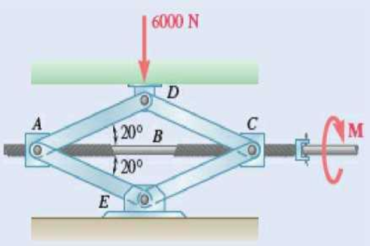
Fig. P8.72
Expert Solution & Answer
Want to see the full answer?
Check out a sample textbook solution
Students have asked these similar questions
Question 6
What kind of problem would arise if components of the strain tensor were defined
as v
please show steps, thanks
You design a pin joint. The pin is made of a material with the yield strength of 325
MPa and ultimate strength of 500 MPa. The maximum allowed stress in service is
expressed as a tensor
0
100 0
σ
100
0
0 MPa
0
0
Evaluate the safety factor SF for stress in this design.
Write answer unitless rounding to 2 decimal places and enter decimals even if those
are zeros.
Chapter 8 Solutions
VECTOR MECH...,STAT.+DYN.(LL)-W/ACCESS
Ch. 8.1 - Knowing that the coefficient of friction between...Ch. 8.1 - Two blocks A and B are connected by a cable as...Ch. 8.1 - A cord is attached to and partially wound around a...Ch. 8.1 - A 40-kg packing crate must be moved to the left...Ch. 8.1 - Determine whether the block shown is in...Ch. 8.1 - Determine whether the block shown is in...Ch. 8.1 - Determine whether the block shown is in...Ch. 8.1 - Determine whether the block shown is in...Ch. 8.1 - Knowing that = 45 in Prob. 8.1, determine the...Ch. 8.1 - The 20-lb block A hangs from a cable as shown....
Ch. 8.1 - The 10-kg block is attached to link AB and rests...Ch. 8.1 - Considering only values of less than 90,...Ch. 8.1 - Prob. 8.9PCh. 8.1 - Prob. 8.10PCh. 8.1 - The 50-lb block A and the 25-lb block B are...Ch. 8.1 - The 50-lb block A and the 25-lb block B are...Ch. 8.1 - Three 4-kg packages A, B, and C are placed on a...Ch. 8.1 - Prob. 8.14PCh. 8.1 - A uniform crate with a mass of 30 kg must be moved...Ch. 8.1 - A worker slowly moves a 50-kg crate to the left...Ch. 8.1 - Prob. 8.17PCh. 8.1 - A 200-lb sliding door is mounted on a horizontal...Ch. 8.1 - Prob. 8.19PCh. 8.1 - Prob. 8.20PCh. 8.1 - Prob. 8.21PCh. 8.1 - Prob. 8.22PCh. 8.1 - The 10-lb uniform rod AB is held in the position...Ch. 8.1 - Prob. 8.24PCh. 8.1 - Prob. 8.25PCh. 8.1 - Prob. 8.26PCh. 8.1 - The press shown is used to emboss a small seal at...Ch. 8.1 - The machine base shown has a mass of 75 kg and is...Ch. 8.1 - Prob. 8.29PCh. 8.1 - Prob. 8.30PCh. 8.1 - Prob. 8.31PCh. 8.1 - Prob. 8.32PCh. 8.1 - Prob. 8.33PCh. 8.1 - A driver starts the engine of an automobile that...Ch. 8.1 - Prob. 8.35PCh. 8.1 - Two uniform rods each of weight W and length L are...Ch. 8.1 - A 1.2-m plank with a mass of 3 kg rests on two...Ch. 8.1 - Two identical uniform boards, each with a weight...Ch. 8.1 - A uniform 20-kg tube resting on a loading dock...Ch. 8.1 - Prob. 8.40PCh. 8.1 - A 10-ft beam, weighing 1200 lb, is to be moved to...Ch. 8.1 - (a) Show that the beam of Prob. 8.41 cannot be...Ch. 8.1 - Two 8-kg blocks A and B resting on shelves are...Ch. 8.1 - Prob. 8.44PCh. 8.1 - Prob. 8.45PCh. 8.1 - Two slender rods of negligible weight are...Ch. 8.1 - Two slender rods of negligible weight are...Ch. 8.2 - The machine part ABC is supported by a...Ch. 8.2 - Prob. 8.49PCh. 8.2 - Prob. 8.50PCh. 8.2 - Prob. 8.51PCh. 8.2 - Prob. 8.52PCh. 8.2 - Solve Prob. 8.52 assuming that the end of the beam...Ch. 8.2 - Prob. 8.54PCh. 8.2 - Prob. 8.55PCh. 8.2 - Block A supports a pipe column and rests as shown...Ch. 8.2 - A 200-lb block rests as shown on a wedge of...Ch. 8.2 - Prob. 8.58PCh. 8.2 - Prob. 8.59PCh. 8.2 - Prob. 8.60PCh. 8.2 - Prob. 8.61PCh. 8.2 - An 8 wedge is to be forced under a machine base at...Ch. 8.2 - Prob. 8.63PCh. 8.2 - A 15 wedge is forced under a 50-kg pipe as shown....Ch. 8.2 - A 15 wedge is forced under a 50-kg pipe as shown....Ch. 8.2 - Prob. 8.66PCh. 8.2 - Prob. 8.67PCh. 8.2 - Prob. 8.68PCh. 8.2 - Prob. 8.69PCh. 8.2 - Prob. 8.70PCh. 8.2 - Prob. 8.71PCh. 8.2 - The position of the automobile jack shown is...Ch. 8.2 - Prob. 8.73PCh. 8.2 - Prob. 8.74PCh. 8.2 - In the vise shown, the screw is single-threaded in...Ch. 8.2 - Prob. 8.76PCh. 8.3 - A lever of negligible weight is loosely fitted...Ch. 8.3 - Prob. 8.78PCh. 8.3 - 8.79 and 8.80 The double pulley shown is attached...Ch. 8.3 - Prob. 8.80PCh. 8.3 - 8.81 and 8.82 The double pulley shown is attached...Ch. 8.3 - Prob. 8.82PCh. 8.3 - Prob. 8.83PCh. 8.3 - The block and tackle shown are used to lower a...Ch. 8.3 - Prob. 8.85PCh. 8.3 - Prob. 8.86PCh. 8.3 - Prob. 8.87PCh. 8.3 - 8.87 and 8.88 A lever AB of negligible weight is...Ch. 8.3 - Prob. 8.89PCh. 8.3 - Prob. 8.90PCh. 8.3 - Prob. 8.91PCh. 8.3 - Prob. 8.92PCh. 8.3 - Prob. 8.93PCh. 8.3 - Prob. 8.94PCh. 8.3 - Prob. 8.95PCh. 8.3 - Prob. 8.96PCh. 8.3 - Solve Prob. 8.93 assuming that the normal force...Ch. 8.3 - Prob. 8.98PCh. 8.3 - Prob. 8.99PCh. 8.3 - A 900-kg machine base is rolled along a concrete...Ch. 8.3 - Prob. 8.101PCh. 8.3 - Prob. 8.102PCh. 8.4 - A rope having a weight per unit length of 0.4...Ch. 8.4 - A hawser is wrapped two full turns around a...Ch. 8.4 - Two cylinders are connected by a rope that passes...Ch. 8.4 - Prob. 8.106PCh. 8.4 - The coefficient of static friction between block B...Ch. 8.4 - Prob. 8.108PCh. 8.4 - A band belt is used to control the speed of a...Ch. 8.4 - Prob. 8.110PCh. 8.4 - The setup shown is used to measure the output of a...Ch. 8.4 - A flat belt is used to transmit a couple from drum...Ch. 8.4 - Prob. 8.113PCh. 8.4 - Prob. 8.114PCh. 8.4 - The speed of the brake drum shown is controlled by...Ch. 8.4 - The speed of the brake drum shown is controlled by...Ch. 8.4 - Prob. 8.117PCh. 8.4 - Bucket A and block C are connected by a cable that...Ch. 8.4 - Prob. 8.119PCh. 8.4 - Prob. 8.120PCh. 8.4 - 8.121 and 8.123 A cable is placed around three...Ch. 8.4 - Prob. 8.122PCh. 8.4 - Prob. 8.123PCh. 8.4 - Prob. 8.124PCh. 8.4 - Prob. 8.125PCh. 8.4 - Prob. 8.126PCh. 8.4 - The axle of the pulley is frozen and cannot rotate...Ch. 8.4 - The 10-lb bar AE is suspended by a cable that...Ch. 8.4 - Prob. 8.129PCh. 8.4 - Prove that Eqs. (8.13) and (8.14) are valid for...Ch. 8.4 - Complete the derivation of Eq. (8.15), which...Ch. 8.4 - Prob. 8.132PCh. 8.4 - Solve Prob. 8.113 assuming that the flat belt and...Ch. 8 - 8.134 and 8.135 The coefficients of friction are S...Ch. 8 - Prob. 8.135RPCh. 8 - Prob. 8.136RPCh. 8 - A slender rod with a length of L is lodged between...Ch. 8 - The hydraulic cylinder shown exerts a force of 3...Ch. 8 - Prob. 8.139RPCh. 8 - Bar AB is attached to collars that can slide on...Ch. 8 - Two 10 wedges of negligible weight are used to...Ch. 8 - A 10 wedge is used to split a section of a log....Ch. 8 - Prob. 8.143RPCh. 8 - A lever of negligible weight is loosely fitted...Ch. 8 - In the pivoted motor mount shown, the weight W of...
Knowledge Booster


Learn more about
Need a deep-dive on the concept behind this application? Look no further. Learn more about this topic, mechanical-engineering and related others by exploring similar questions and additional content below.Similar questions
- 2. A single crystal of aluminum is oriented for a tensile test such that its slip plane normal makes an angle of 28.1° with the tensile axis. Three possible slip directions make angles of 62.4°, 72.0°, and 81.1° with the same tensile axis. (a) Which of these three slip directions is most favored? (b) If plastic deformation begins at a tensile stress of σ x = 1.95 MPa (280 psi), determine the critical resolved shear stress for aluminium. (c) If this single crystalspecimen is loaded under the new stress state: σ x =1.2 MPa σ y = -0.8 MPa, and τ xy = 0.6 MPa, howmuch is the resolve the shear stress along the most favored slip direction?arrow_forwardPlease explain how to do each part and tell me if my drawing is correct. thank youarrow_forward4. Determine which of the following flow fields represent a possible incompressible flow? (a) u= x²+2y+z; v=x-2y+z;w= -2xy + y² + 2z a (b) V=U cose U coso 1 (9) [1-9] Usino |1 (4)] [+] V=-Usin 1+1arrow_forward
- 3. Determine the flow rate through the pipe line show in the figure in ft³/s, and determine the pressures at A and C, in psi. 5' B C 12° 20' D 6"d 2nd- Water Aarrow_forward5. A flow is field given by V = x²₁³+xy, and determine 3 ·y³j- (a) Whether this is a one, two- or three-dimensional flow (b) Whether it is a possible incompressible flow (c) Determine the acceleration of a fluid particle at the location (X,Y,Z)=(1,2,3) (d) Whether the flow is rotational or irrotational flow?arrow_forwardSolve this problem and show all of the workarrow_forward
- Solve this problem and show all of the workarrow_forwarddraw the pneumatic circuit to operate a double-acting cylinder with: 1. Extension: Any of two manual conditions plus cylinder fully retracted, → Extension has both meter-in and meter-out, 2. Retraction: one manual conditions plus cylinder fully extended, → Retraction is very fast using quick exhaust valve.arrow_forwardCorrect answer is written below. Detailed and complete solution with fbd only. I will upvote, thank you. Expert solution plsarrow_forward
- Correct answer is written below. Detailed and complete solution with fbd only. I will upvote, thank you.arrow_forwardCorrect answer is written below. Detailed and complete solution with fbd only. I will upvote, thank you.arrow_forwardCorrect answer is written below. Detailed and complete solution only with fbd. I will upvote, thank you.arrow_forward
arrow_back_ios
SEE MORE QUESTIONS
arrow_forward_ios
Recommended textbooks for you
 Elements Of ElectromagneticsMechanical EngineeringISBN:9780190698614Author:Sadiku, Matthew N. O.Publisher:Oxford University Press
 Mechanics of Materials (10th Edition)Mechanical EngineeringISBN:9780134319650Author:Russell C. HibbelerPublisher:PEARSON
 Thermodynamics: An Engineering ApproachMechanical EngineeringISBN:9781259822674Author:Yunus A. Cengel Dr., Michael A. BolesPublisher:McGraw-Hill Education
 Control Systems EngineeringMechanical EngineeringISBN:9781118170519Author:Norman S. NisePublisher:WILEY
 Mechanics of Materials (MindTap Course List)Mechanical EngineeringISBN:9781337093347Author:Barry J. Goodno, James M. GerePublisher:Cengage Learning
 Engineering Mechanics: StaticsMechanical EngineeringISBN:9781118807330Author:James L. Meriam, L. G. Kraige, J. N. BoltonPublisher:WILEY
Elements Of Electromagnetics
Mechanical Engineering
ISBN:9780190698614
Author:Sadiku, Matthew N. O.
Publisher:Oxford University Press
Mechanics of Materials (10th Edition)
Mechanical Engineering
ISBN:9780134319650
Author:Russell C. Hibbeler
Publisher:PEARSON
Thermodynamics: An Engineering Approach
Mechanical Engineering
ISBN:9781259822674
Author:Yunus A. Cengel Dr., Michael A. Boles
Publisher:McGraw-Hill Education
Control Systems Engineering
Mechanical Engineering
ISBN:9781118170519
Author:Norman S. Nise
Publisher:WILEY
Mechanics of Materials (MindTap Course List)
Mechanical Engineering
ISBN:9781337093347
Author:Barry J. Goodno, James M. Gere
Publisher:Cengage Learning
Engineering Mechanics: Statics
Mechanical Engineering
ISBN:9781118807330
Author:James L. Meriam, L. G. Kraige, J. N. Bolton
Publisher:WILEY
How to balance a see saw using moments example problem; Author: Engineer4Free;https://www.youtube.com/watch?v=d7tX37j-iHU;License: Standard Youtube License