
VECTOR MECH...,STAT.+DYN.(LL)-W/ACCESS
12th Edition
ISBN: 9781260265453
Author: BEER
Publisher: MCG
expand_more
expand_more
format_list_bulleted
Videos
Textbook Question
Chapter 8.1, Problem 8.15P
A uniform crate with a mass of 30 kg must be moved up along the 15° incline without tipping. Knowing that force P is horizontal, determine (a) the largest allowable coefficient of static friction between the crate and the incline, (b) the corresponding magnitude of force P.
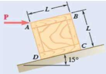
Fig. P8.15
Expert Solution & Answer
Want to see the full answer?
Check out a sample textbook solution
Students have asked these similar questions
Problem 9.5
9.5 A 1080-kg car is parked on a sloped street. The figure shows its wheels and the position of
its center of mass. The street is icy, and as a result the coefficient of static friction between
the car's tires and the street surface is μs = 0.2. Determine the steepest slope (in degrees
relative to the horizontal) at which the car could remain in equilibrium if
a. the brakes are applied to both its front and rear wheels;
b. the brakes are applied to the front (lower) wheels only.
Problem 9.5
1380 mm
532 mm
2370 mm
Can someone explain please with conversions
Correct Answer is written below. Detailed and complete fbd only please. I will upvote, thank you.
1: The assembly shown is composed of a rigid plank ABC, supported by hinge at A, spring at B and cable at C.The cable is attached to a frictionless pulley at D and rigidly supported at E. The cable is made of steel with E = 200,000MPa and cross-sectional area of 500 mm2. The details of pulley at D is shown. The pulley is supported by a pin, passingthough the pulley and attached to both cheeks. Note that E is directly above B.Given: H = 3 m; L1 = 2 m; L2 = 4 m; w = 12 kN/m; x:y = 3:4Spring Parameters:Wire diameter = 30 mmMean Radius = 90 mmNumber of turns = 12Modulus of Rigidity = 80 GPaAllowable stresses:Allowable shear stress of Pin at D = 85 MPaAllowable normal stress of cheek at D = 90MPaAllowable bearing stress of cheek at D = 110MPa1. Calculate the reaction of spring Band tension in cable at C.2. Calculate the vertical displacementat C and the required diameter ofpin at D.3.…
Chapter 8 Solutions
VECTOR MECH...,STAT.+DYN.(LL)-W/ACCESS
Ch. 8.1 - Knowing that the coefficient of friction between...Ch. 8.1 - Two blocks A and B are connected by a cable as...Ch. 8.1 - A cord is attached to and partially wound around a...Ch. 8.1 - A 40-kg packing crate must be moved to the left...Ch. 8.1 - Determine whether the block shown is in...Ch. 8.1 - Determine whether the block shown is in...Ch. 8.1 - Determine whether the block shown is in...Ch. 8.1 - Determine whether the block shown is in...Ch. 8.1 - Knowing that = 45 in Prob. 8.1, determine the...Ch. 8.1 - The 20-lb block A hangs from a cable as shown....
Ch. 8.1 - The 10-kg block is attached to link AB and rests...Ch. 8.1 - Considering only values of less than 90,...Ch. 8.1 - Prob. 8.9PCh. 8.1 - Prob. 8.10PCh. 8.1 - The 50-lb block A and the 25-lb block B are...Ch. 8.1 - The 50-lb block A and the 25-lb block B are...Ch. 8.1 - Three 4-kg packages A, B, and C are placed on a...Ch. 8.1 - Prob. 8.14PCh. 8.1 - A uniform crate with a mass of 30 kg must be moved...Ch. 8.1 - A worker slowly moves a 50-kg crate to the left...Ch. 8.1 - Prob. 8.17PCh. 8.1 - A 200-lb sliding door is mounted on a horizontal...Ch. 8.1 - Prob. 8.19PCh. 8.1 - Prob. 8.20PCh. 8.1 - Prob. 8.21PCh. 8.1 - Prob. 8.22PCh. 8.1 - The 10-lb uniform rod AB is held in the position...Ch. 8.1 - Prob. 8.24PCh. 8.1 - Prob. 8.25PCh. 8.1 - Prob. 8.26PCh. 8.1 - The press shown is used to emboss a small seal at...Ch. 8.1 - The machine base shown has a mass of 75 kg and is...Ch. 8.1 - Prob. 8.29PCh. 8.1 - Prob. 8.30PCh. 8.1 - Prob. 8.31PCh. 8.1 - Prob. 8.32PCh. 8.1 - Prob. 8.33PCh. 8.1 - A driver starts the engine of an automobile that...Ch. 8.1 - Prob. 8.35PCh. 8.1 - Two uniform rods each of weight W and length L are...Ch. 8.1 - A 1.2-m plank with a mass of 3 kg rests on two...Ch. 8.1 - Two identical uniform boards, each with a weight...Ch. 8.1 - A uniform 20-kg tube resting on a loading dock...Ch. 8.1 - Prob. 8.40PCh. 8.1 - A 10-ft beam, weighing 1200 lb, is to be moved to...Ch. 8.1 - (a) Show that the beam of Prob. 8.41 cannot be...Ch. 8.1 - Two 8-kg blocks A and B resting on shelves are...Ch. 8.1 - Prob. 8.44PCh. 8.1 - Prob. 8.45PCh. 8.1 - Two slender rods of negligible weight are...Ch. 8.1 - Two slender rods of negligible weight are...Ch. 8.2 - The machine part ABC is supported by a...Ch. 8.2 - Prob. 8.49PCh. 8.2 - Prob. 8.50PCh. 8.2 - Prob. 8.51PCh. 8.2 - Prob. 8.52PCh. 8.2 - Solve Prob. 8.52 assuming that the end of the beam...Ch. 8.2 - Prob. 8.54PCh. 8.2 - Prob. 8.55PCh. 8.2 - Block A supports a pipe column and rests as shown...Ch. 8.2 - A 200-lb block rests as shown on a wedge of...Ch. 8.2 - Prob. 8.58PCh. 8.2 - Prob. 8.59PCh. 8.2 - Prob. 8.60PCh. 8.2 - Prob. 8.61PCh. 8.2 - An 8 wedge is to be forced under a machine base at...Ch. 8.2 - Prob. 8.63PCh. 8.2 - A 15 wedge is forced under a 50-kg pipe as shown....Ch. 8.2 - A 15 wedge is forced under a 50-kg pipe as shown....Ch. 8.2 - Prob. 8.66PCh. 8.2 - Prob. 8.67PCh. 8.2 - Prob. 8.68PCh. 8.2 - Prob. 8.69PCh. 8.2 - Prob. 8.70PCh. 8.2 - Prob. 8.71PCh. 8.2 - The position of the automobile jack shown is...Ch. 8.2 - Prob. 8.73PCh. 8.2 - Prob. 8.74PCh. 8.2 - In the vise shown, the screw is single-threaded in...Ch. 8.2 - Prob. 8.76PCh. 8.3 - A lever of negligible weight is loosely fitted...Ch. 8.3 - Prob. 8.78PCh. 8.3 - 8.79 and 8.80 The double pulley shown is attached...Ch. 8.3 - Prob. 8.80PCh. 8.3 - 8.81 and 8.82 The double pulley shown is attached...Ch. 8.3 - Prob. 8.82PCh. 8.3 - Prob. 8.83PCh. 8.3 - The block and tackle shown are used to lower a...Ch. 8.3 - Prob. 8.85PCh. 8.3 - Prob. 8.86PCh. 8.3 - Prob. 8.87PCh. 8.3 - 8.87 and 8.88 A lever AB of negligible weight is...Ch. 8.3 - Prob. 8.89PCh. 8.3 - Prob. 8.90PCh. 8.3 - Prob. 8.91PCh. 8.3 - Prob. 8.92PCh. 8.3 - Prob. 8.93PCh. 8.3 - Prob. 8.94PCh. 8.3 - Prob. 8.95PCh. 8.3 - Prob. 8.96PCh. 8.3 - Solve Prob. 8.93 assuming that the normal force...Ch. 8.3 - Prob. 8.98PCh. 8.3 - Prob. 8.99PCh. 8.3 - A 900-kg machine base is rolled along a concrete...Ch. 8.3 - Prob. 8.101PCh. 8.3 - Prob. 8.102PCh. 8.4 - A rope having a weight per unit length of 0.4...Ch. 8.4 - A hawser is wrapped two full turns around a...Ch. 8.4 - Two cylinders are connected by a rope that passes...Ch. 8.4 - Prob. 8.106PCh. 8.4 - The coefficient of static friction between block B...Ch. 8.4 - Prob. 8.108PCh. 8.4 - A band belt is used to control the speed of a...Ch. 8.4 - Prob. 8.110PCh. 8.4 - The setup shown is used to measure the output of a...Ch. 8.4 - A flat belt is used to transmit a couple from drum...Ch. 8.4 - Prob. 8.113PCh. 8.4 - Prob. 8.114PCh. 8.4 - The speed of the brake drum shown is controlled by...Ch. 8.4 - The speed of the brake drum shown is controlled by...Ch. 8.4 - Prob. 8.117PCh. 8.4 - Bucket A and block C are connected by a cable that...Ch. 8.4 - Prob. 8.119PCh. 8.4 - Prob. 8.120PCh. 8.4 - 8.121 and 8.123 A cable is placed around three...Ch. 8.4 - Prob. 8.122PCh. 8.4 - Prob. 8.123PCh. 8.4 - Prob. 8.124PCh. 8.4 - Prob. 8.125PCh. 8.4 - Prob. 8.126PCh. 8.4 - The axle of the pulley is frozen and cannot rotate...Ch. 8.4 - The 10-lb bar AE is suspended by a cable that...Ch. 8.4 - Prob. 8.129PCh. 8.4 - Prove that Eqs. (8.13) and (8.14) are valid for...Ch. 8.4 - Complete the derivation of Eq. (8.15), which...Ch. 8.4 - Prob. 8.132PCh. 8.4 - Solve Prob. 8.113 assuming that the flat belt and...Ch. 8 - 8.134 and 8.135 The coefficients of friction are S...Ch. 8 - Prob. 8.135RPCh. 8 - Prob. 8.136RPCh. 8 - A slender rod with a length of L is lodged between...Ch. 8 - The hydraulic cylinder shown exerts a force of 3...Ch. 8 - Prob. 8.139RPCh. 8 - Bar AB is attached to collars that can slide on...Ch. 8 - Two 10 wedges of negligible weight are used to...Ch. 8 - A 10 wedge is used to split a section of a log....Ch. 8 - Prob. 8.143RPCh. 8 - A lever of negligible weight is loosely fitted...Ch. 8 - In the pivoted motor mount shown, the weight W of...
Knowledge Booster


Learn more about
Need a deep-dive on the concept behind this application? Look no further. Learn more about this topic, mechanical-engineering and related others by exploring similar questions and additional content below.Similar questions
- Correct answer and complete fbd only. I will upvote. The compound shaft, composed of steel,aluminum, and bronze segments, carries the two torquesshown in the figure. If TC = 250 lb-ft, determine the maximumshear stress developed in each material (in ksi). The moduliof rigidity for steel, aluminum, and bronze are 12 x 106 psi, 4x 10⁶ psi, and 6 x 10⁶ psi, respectivelyarrow_forwardCan you explain the algebra steps that aren't shown but stated to be there, on how to get this equationarrow_forwardCorrect answer and complete fbd only. I will upvote. A flanged bolt coupling consists of two concentric rows of bolts. The inner row has 6 nos. of 16mm diameterbolts spaced evenly in a circle of 250mm in diameter. The outer row of has 10 nos. of 25 mm diameter bolts spaced evenly in a circle of 500mm in diameter. If the allowable shear stress on one bolt is 60 MPa, determine the torque capacity of the coupling. The Poisson’s ratio of the inner row of bolts is 0.2 while that of the outer row is 0.25 and the bolts are steel, E =200 GPa.arrow_forward
- Correct answer and complete fbd only. I will upvote. 10: The constant wall thickness of a steel tube with the cross sectionshown is 2 mm. If a 600-N-m torque is applied to the tube. Use G = 80 GPa forsteel.1. Find the shear stress (MPa) in the wall of the tube.2. Find the angle of twist, in degrees per meter of length.arrow_forwardCORRECT ANSWER WITH COMPLETE FBD ONLY. I WILL UPVOTE. A torque wrench is used to tighten the pipe shown.Dimensions: S1 = 400 mm; S2 = 250 mm; S3 = 100 mmModulus of Rigidity G = 78 GPa1. The diameter of the solid pipe is 20 mm. How much is themaximum force P (N) that can be applied based on theallowable shear stress of 60 MPa?2. For a hollow pipe with 50 mm outside diameter and is 6 mmthick, compute for the maximum force P (kN) that can beapplied such that the angle of twist at A does not exceed 5degrees.3. The torque applied to tighten the hollow pipe is 200 N-m.Given: Pipe outside diameter = 50 mm Pipe thickness = 6 mmSolve for the resulting maximum shear stress (MPa) in the pipe.arrow_forwardCorrect answer and complete fbd only. I will upvote. 6: The shaft carries a total torque T0 that is uniformly distributedover its length L. Determine the angle of twist (degrees) of the shaft in termsif T0 = 1.2 kN-m, L = 2 m, G = 80 GPa, and diameter = 120 mm.arrow_forward
- 2. Calculate the force in all members of the trusses shown using the method of joints. A 5525 lb C 3500 lb BY 14'-0" D 10'- 0" 6250 lb 10'- 0" Earrow_forwardCorrect answer and complete fbd only. I will upvote. 8: The steel rod fits loosely inside the aluminum sleeve. Both components are attached to a rigid wall at A andjoined together by a pin at B. Because of a slight misalignmentof the pre-drilled holes, the torque T0 = 750 N-m was appliedto the steel rod before the pin could be inserted into theholes. Determine the torque (N-m) in each component afterT0 was removed. Use G = 80 GPa for steel and G = 28 GPa foraluminumarrow_forwardCorrect answer and complete fbd only. I will upvote. 9: The two steel shafts, each with one end builtinto a rigid support, have flanges attached to their freeends. The flanges are to be bolted together. However,initially there is a 6⁰ mismatch in the location of the boltholes as shown in the figure. Determine the maximumshear stress(ksi) in each shaft after the flanges have beenbolted together. The shear modulus of elasticity for steelis 12 x 106 psi. Neglect deformations of the bolts and theflanges.arrow_forward
- Correct answer and complete fbd only. I will upvote. The tapered, wrought iron shaft carriesthe torque T = 2000 lb-in at its free end. Determine theangle of twist (degrees) of the shaft. Use G = 10 x 106psi for wrought ironarrow_forwardCorrect answer and complete fbd only. I will upvote. The compound shaft, consisting of steel and aluminumsegments, carries the two torques shown in the figure. Determine themaximum permissible value of T subject to the following designconditions: τst ≤ 83 MPa, τal ≤ 55 MPa, and θ ≤ 6⁰ (θ is the angle ofrotation of the free end). Use G =83 GPa for steel and G = 28 GPa foraluminum.arrow_forwardThe solid compound shaft, made of threedifferent materials, carries the two torques shown. Theshear moduli are 28 GPa for aluminum, 83 GPa for steel,and 35 GPa for bronze.1. Calculate the maximum shear stress (MPa) in eachmaterial.2. Find the angle of rotation (degrees) of the free endof the shaft.arrow_forward
arrow_back_ios
SEE MORE QUESTIONS
arrow_forward_ios
Recommended textbooks for you
 Elements Of ElectromagneticsMechanical EngineeringISBN:9780190698614Author:Sadiku, Matthew N. O.Publisher:Oxford University Press
 Mechanics of Materials (10th Edition)Mechanical EngineeringISBN:9780134319650Author:Russell C. HibbelerPublisher:PEARSON
 Thermodynamics: An Engineering ApproachMechanical EngineeringISBN:9781259822674Author:Yunus A. Cengel Dr., Michael A. BolesPublisher:McGraw-Hill Education
 Control Systems EngineeringMechanical EngineeringISBN:9781118170519Author:Norman S. NisePublisher:WILEY
 Mechanics of Materials (MindTap Course List)Mechanical EngineeringISBN:9781337093347Author:Barry J. Goodno, James M. GerePublisher:Cengage Learning
 Engineering Mechanics: StaticsMechanical EngineeringISBN:9781118807330Author:James L. Meriam, L. G. Kraige, J. N. BoltonPublisher:WILEY
Elements Of Electromagnetics
Mechanical Engineering
ISBN:9780190698614
Author:Sadiku, Matthew N. O.
Publisher:Oxford University Press
Mechanics of Materials (10th Edition)
Mechanical Engineering
ISBN:9780134319650
Author:Russell C. Hibbeler
Publisher:PEARSON
Thermodynamics: An Engineering Approach
Mechanical Engineering
ISBN:9781259822674
Author:Yunus A. Cengel Dr., Michael A. Boles
Publisher:McGraw-Hill Education
Control Systems Engineering
Mechanical Engineering
ISBN:9781118170519
Author:Norman S. Nise
Publisher:WILEY
Mechanics of Materials (MindTap Course List)
Mechanical Engineering
ISBN:9781337093347
Author:Barry J. Goodno, James M. Gere
Publisher:Cengage Learning
Engineering Mechanics: Statics
Mechanical Engineering
ISBN:9781118807330
Author:James L. Meriam, L. G. Kraige, J. N. Bolton
Publisher:WILEY
How to balance a see saw using moments example problem; Author: Engineer4Free;https://www.youtube.com/watch?v=d7tX37j-iHU;License: Standard Youtube License