
Videos
Two 8-kg blocks A and B resting on shelves are connected by a rod of negligible mass. Knowing that the magnitude of a horizontal force P applied at C is slowly increased from zero, determine the value of P for which motion occurs and what that motion is when the coefficient of static friction between all surfaces is (a) μs = 0.40, (b) μs = 0.50.
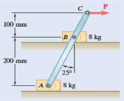
Fig. P8.43
(a)
Find the magnitude of horizontal force P applied at C for which the motion occurs.
Answer to Problem 8.43P
The magnitude of the horizontal force P is
The system
Explanation of Solution
Given information:
The mass of the blocks A and B is
The coefficient of static friction between the surfaces is
Calculation:
Consider the blocks will slide to the right.
Find the weight (W) of the blocks A and B using the relation.
Here, the acceleration due to gravity is g.
Consider the acceleration due to gravity is
Substitute 8 kg for m and
Find the friction force at block A and B as follows.
Here, the normal force at block A is
Show the free-body diagram of the shelves as in Figure 1.
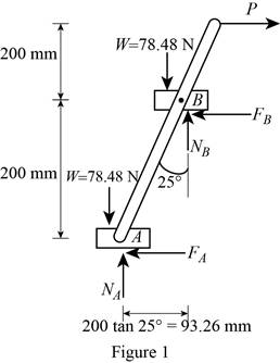
Resolve the vertical component of forces.
Resolve the horizontal component of forces.
Substitute 0.40 for
Therefore, the magnitude of the horizontal force P is
Take moment about point B.
Substitute 62.8 N for P and 0.40 for
Therefore, the system
(b)
Find the magnitude of horizontal force P applied at C for which the motion occurs.
Answer to Problem 8.43P
The
The magnitude of the horizontal force P is
Explanation of Solution
Given information:
The mass of the blocks A and B is
The coefficient of static friction between the surfaces is
Calculation:
Consider the blocks will slide to the right.
Find the weight (W) of the blocks A and B using the relation.
Here, the acceleration due to gravity is g.
Consider the acceleration due to gravity is
Substitute 8 kg for m and
Find the friction force at block A and B as follows.
Here, the normal force at block A is
Resolve the vertical component of forces.
Resolve the horizontal component of forces.
Substitute 0.50 for
Therefore, the magnitude of the horizontal force P is
Take moment about point B.
Substitute 78.48 N for P and 0.50 for
Therefore, the
The value of
Take moment about point B.
Substitute 0 for
Therefore, the magnitude of the horizontal force P is
Want to see more full solutions like this?
Chapter 8 Solutions
VECTOR MECH...,STAT.+DYN.(LL)-W/ACCESS


- Assume multiple single degree of freedom systems with natural periods T ∈ [0.05, 2.00] seconds with in-crement of period dT = 0.05 seconds. Assume three cases of damping ratio: Case (A) ξ = 0%; Case (B)ξ = 2%; Case (C) ξ = 5%. The systems are initially at rest. Thus, the initial conditions are u(t = 0) = 0 anḋu(t = 0) = 0. The systems are subjected to the base acceleration that was provided in the ElCentro.txt file(i.e., first column). For the systems in Case (A), Case (B), and Case (C) and for each natural period computethe peak acceleration, peak velocity, and peak displacement responses to the given base excitation. Please,use the Newmark method for β = 1/4 (average acceleration) to compute the responses. Create threeplots with three lines in each plot. The first plot will have the peak accelerations in y-axis and the naturalperiod of the system in x-axis. The second plot will have the peak velocities in y-axis and the natural periodof the system in x-axis. The third plot will have…arrow_forwardBoth portions of the rod ABC are made of an aluminum for which E = 70 GPa. Based on the given information find: 1- deformation at A 2- stress in BC 3- Total strain 4- If v (Poisson ratio is 0.25, find the lateral deformation of AB Last 3 student ID+ 300 mm=L2 724 A P=Last 2 student ID+ 300 KN 24 24 Diameter Last 2 student ID+ 15 mm Last 3 student ID+ 500 mm=L1 724 C B 24 Q=Last 2 student ID+ 100 KN 24 Diameter Last 2 student ID+ 40 mmarrow_forwardQ2Two wooden members of uniform cross section are joined by the simple scarf splice shown. Knowing that the maximum allowable tensile stress in the glued splice is 75 psi, determine (a) the largest load P that can be safely supported, (b) the corresponding shearing stress in the splice. น Last 1 student ID+5 inch=W =9 4 L=Last 1 student ID+8 inch =12 60° P'arrow_forward
- Q4 The two solid shafts are connected by gears as shown and are made of a steel for which the allowable shearing stress is 7000 psi. Knowing the diameters of the two shafts are, respectively, dBC determine the largest torque Tc that can be applied at C. 4 and dEF dBC=Last 1 student ID+3 inch dEF=Last 1 student ID+1 inch 7 R=Last 1 Student ID+5 inch 9 R B Tc 2.5 in. E TF Harrow_forwardExperiment تكنولوجيا السيارات - Internal Forced convenction Heat transfer Air Flow through Rectangular Duct. objective: Study the convection heat transfer of air flow through rectangular duct. Valve Th Top Dead Centre Exhaust Valve Class CP. N; ~ RIVavg Ti K 2.11 Te To 18.8 21.3 45.8 Nath Ne Pre Calculations:. Q = m cp (Te-Ti) m: Varg Ac Acca*b Q=hexp As (Ts-Tm) 2 2.61 18.5 20.846.3 Tm = Te-Ti = 25 AS-PL = (a+b)*2*L Nu exp= Re-Vavy D heep Dh k 2ab a+b Nu Dh the- (TS-Tm) Ts. Tmy Name / Nu exp Naxe بب ارتدان العشريarrow_forwardProcedure:1- Cartesian system, 2D3D,type of support2- Free body diagram3 - Find the support reactions4- If you find a negativenumber then flip the force5- Find the internal force3D∑Fx=0∑Fy=0∑Fz=0∑Mx=0∑My=0\Sigma Mz=02D\Sigma Fx=0\Sigma Fy=0\Sigma Mz=05- Use method of sectionand cut the elementwhere you want to findarrow_forward
- Procedure:1- Cartesian system, 2D3D,type of support2- Free body diagram3 - Find the support reactions4- If you find a negativenumber then flip the force5- Find the internal force3D∑Fx=0∑Fy=0∑Fz=0∑Mx=0∑My=0\Sigma Mz=02D\Sigma Fx=0\Sigma Fy=0\Sigma Mz=05- Use method of sectionand cut the elementwhere you want to findthe internal force andkeep either side of thearrow_forwardProcedure: 1- Cartesian system, 2D3D, type of support 2- Free body diagram 3 - Find the support reactions 4- If you find a negative number then flip the force 5- Find the internal force 3D ∑Fx=0 ∑Fy=0 ∑Fz=0 ∑Mx=0 ∑My=0 ΣMz=0 2D ΣFx=0 ΣFy=0 ΣMz=0 5- Use method of section and cut the element where you want to find the internal force and keep either side of thearrow_forwardProcedure:1- Cartesian system, 2D3D,type of support2- Free body diagram3 - Find the support reactions4- If you find a negativenumber then flip the force5- Find the internal force3D∑Fx=0∑Fy=0∑Fz=0∑Mx=0∑My=0\Sigma Mz=02D\Sigma Fx=0\Sigma Fy=0\Sigma Mz=05- Use method of sectionand cut the elementwhere you want to findthe internal force andkeep either side of thearrow_forward
- Procedure: 1- Cartesian system, 2(D)/(3)D, type of support 2- Free body diagram 3 - Find the support reactions 4- If you find a negative number then flip the force 5- Find the internal force 3D \sum Fx=0 \sum Fy=0 \sum Fz=0 \sum Mx=0 \sum My=0 \Sigma Mz=0 2D \Sigma Fx=0 \Sigma Fy=0 \Sigma Mz=0 5- Use method of section and cut the element where you want to find the internal force and keep either side of the sectionarrow_forwardProcedure: 1- Cartesian system, 2(D)/(3)D, type of support 2- Free body diagram 3 - Find the support reactions 4- If you find a negative number then flip the force 5- Find the internal force 3D \sum Fx=0 \sum Fy=0 \sum Fz=0 \sum Mx=0 \sum My=0 \Sigma Mz=0 2D \Sigma Fx=0 \Sigma Fy=0 \Sigma Mz=0 5- Use method of section and cut the element where you want to find the internal force and keep either side of the sectionarrow_forwardFor each system below with transfer function G(s), plot the pole(s) on the s-plane. and indicate whether the system is: (a) "stable" (i.e., a bounded input will always result in a bounded output), (b) "marginally stable," or (c) "unstable" Sketch a rough graph of the time response to a step input. 8 a) G(s) = 5-5 8 b) G(s) = c) G(s) = = s+5 3s + 8 s² - 2s +2 3s +8 d) G(s): = s²+2s+2 3s+8 e) G(s): = s² +9 f) G(s): 8 00 == Sarrow_forward
 Elements Of ElectromagneticsMechanical EngineeringISBN:9780190698614Author:Sadiku, Matthew N. O.Publisher:Oxford University Press
 Mechanics of Materials (10th Edition)Mechanical EngineeringISBN:9780134319650Author:Russell C. HibbelerPublisher:PEARSON
 Thermodynamics: An Engineering ApproachMechanical EngineeringISBN:9781259822674Author:Yunus A. Cengel Dr., Michael A. BolesPublisher:McGraw-Hill Education
 Control Systems EngineeringMechanical EngineeringISBN:9781118170519Author:Norman S. NisePublisher:WILEY
 Mechanics of Materials (MindTap Course List)Mechanical EngineeringISBN:9781337093347Author:Barry J. Goodno, James M. GerePublisher:Cengage Learning
 Engineering Mechanics: StaticsMechanical EngineeringISBN:9781118807330Author:James L. Meriam, L. G. Kraige, J. N. BoltonPublisher:WILEY