
Videos
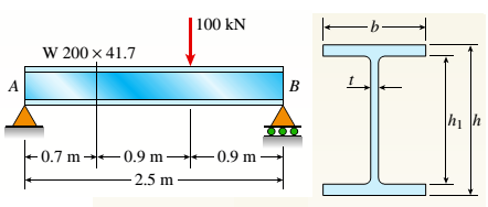
A W 200 x 41.7 wide-flange beam (see Table F-l(b), Appendix F) is simply supported with a span length of 2.5 m (see figure). The beam supports a concentrated load of 100 kN at 0.9 m from support B. At a cross section located 0,7 m from the left-hand support, determine the principal stresses tr, and
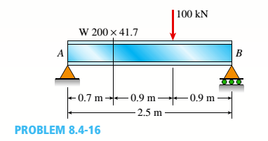
(a).
To find: Values of maximum stress and principal shear stress at top of beam.
Answer to Problem 8.4.16P
Values of principal stress :
Maximum shear stress
Explanation of Solution
Given Information:
Beam length
Point load
Dimensions of beam,
Concept Used:
Bending stress
Shear stress
Values of principal normal stress :
Maximum shear stress:
From equilibrium:
So, bending moment at point
Shear force at point
Moment of inertia:
First, moment of area at the top of beam shall be zero,
So, bending stress at top:
And shear stress at that point:
For this situation no stress in
Values of Principal and normal stress are given by following equation:
Maximum shear stress:
Conclusion:
Hence, we get:
Values of principal stress :
Maximum shear stress
(b).
To find: The values of principal stress and principal stress at top of web.
Answer to Problem 8.4.16P
Values of principal stress:
Maximum shear stress:
Explanation of Solution
Given Information:
Beam length
Point load
Dimensions of beam,
Concept Used:
Bending stress
Shear stress
Values of principal normal stress:
Maximum shear stress

From equilibrium:
So, bending moment at point
Shear force at point
Moment of inertia:
First, moment of area of flange:
So, bending stress at top of web:
And shear stress at that point ::
For this situation no stress in
Values of principal normal stress are given by following equation:
Maximum shear stress,
Conclusion:
Hence, we get:
Values of principal stress :
Maximum shear stress
(c).
To find: Values of principal stress and maximum stress at neutral axis.
Answer to Problem 8.4.16P
Values of principal stress:
Maximum shear stress
Explanation of Solution
Given Information:
Beam length
Point load
Dimensions of beam:
Concept Used:
Bending stress
Shear stress
Principal normal stresses
Maximum shear stress

From equilibrium:
So, bending moment at point
Shear force at point
Moment of inertia,
First moment of area for the section above the neutral axis:
So, bending stress at neutral axis:
And shear stress at that point:
For this situation no stress in
Values of principal stress are given by following equation:
Maximum shear stress:
Conclusion:
Hence, we get:
Values of principal stress:
Maximum shear stress
Want to see more full solutions like this?
Chapter 8 Solutions
Mechanics of Materials, SI Edition


- Solve this probem and show all of the workarrow_forwardThe differential equation of a cruise control system is provided by the following equation: WRITE OUT SOLUTION DO NOT USE A COPIED SOLUTION Find the closed loop transfer function with respect to the reference velocity (vr) . a. Find the poles of the closed loop transfer function for different values of K. How does the poles move as you change K? b. Find the step response for different values of K and plot in MATLAB. What can you observe?arrow_forwardSolve this problem and show all of the workarrow_forward
- Determine the minimum applied force P required to move wedge A to the right. The spring is compressed a distance of 175 mm. Neglect the weight of A and B. The coefficient of static friction for all contacting surface is μs = 0.35. Neglect friction at the rollers. k = = 15 kN/m P A B 10°arrow_forwardDO NOT COPY SOLUTION- will report The differential equation of a cruise control system is provided by the following equation: Find the closed loop transfer function with respect to the reference velocity (vr) . a. Find the poles of the closed loop transfer function for different values of K. How does the poles move as you change K? b. Find the step response for different values of K and plot in MATLAB. What can you observe?arrow_forwarda box shaped barge 37m long, 6.4 m beam, floats at an even keel draught of 2.5 m in water density 1.025 kg/m3. If a mass is added and the vessel moves into water density 1000 kg/m3, determine the magnitude of this mass if the fore end and aft end draughts are 2.4m and 3.8m respectively.arrow_forward
- a ship 125m long and 17.5m beam floats in seawater of 1.025 t/m3 at a draught of 8m. the waterplane coefficient is 0.83, block coefficient 0.759 and midship section area coefficient 0.98. calculate i) prismatic coefficient ii) TPC iii) change in mean draught if the vessel moves into water of 1.016 t/m3arrow_forwardc. For the given transfer function, find tp, ts, tr, Mp . Plot the resulting step response. G(s) = 40/(s^2 + 4s + 40) handplot only, and solve for eacharrow_forwardA ship of 9000 tonne displacement floats in fresh water of 1.000 t/m3 at a draught 50 mm below the sea water line. The waterplane area is 1650 m2. Calculate the mass of cargo which must be added so that when entering seawater of 1.025 t/m3 it floats at the seawater line.arrow_forward
- A ship of 15000 tonne displacement floats at a draught of 7 metres in water of 1.000t/cub. Metre.It is required to load the maximum amount of oil to give the ship a draught of 7.0 metre in seawater ofdensity 1.025 t/cub.metre. If the waterplane area is 2150 square metre, calculate the massof oil requiredarrow_forwardA ship of 8000 tonne displacement floats in seawater of 1.025 t/m3 and has a TPC of 14. The vessel moves into fresh water of 1.000 t/m3 and loads 300 tonne of oil fuel. Calculate the change in mean draught.arrow_forwardAuto Controls DONT COPY ANSWERS - will report Perform the partial fraction expansion of the following transfer function and find the impulse response: G(s) = (s/2 + 5/3) / (s^2 + 4s + 6) G(s) =( 6s^2 + 50) / (s+3)(s^2 +4)arrow_forward
 Mechanics of Materials (MindTap Course List)Mechanical EngineeringISBN:9781337093347Author:Barry J. Goodno, James M. GerePublisher:Cengage Learning