
Videos
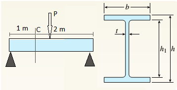
A beam with a wide-flange cross section (see figure) has the following dimensions: h = 120 mm, r = 10 mm, h = 300 mm, and /ij = 260 mm. The beam is simply supported with span length L = 3,0 im A concentrated load P = 120 kN acts at the midpoint of the span.
At across section located 1.0 m from the left-hand support, determine the principal stresses tr, and tr2and the maximum shear stress Tmax at each of the following locations: (a) the top of the beam, (b) the top of the web, and (c) the neutral axis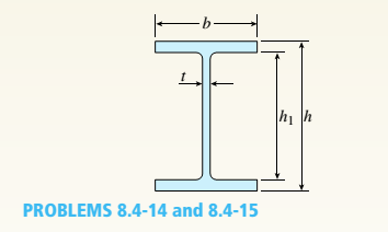
(a).
Find principal stresses and maximum shear stress at top of beam.
Answer to Problem 8.4.14P
Principal stresses
Maximum shear stress
Explanation of Solution
Given Information:
Beam length
Point load
Concept Used:
Bending stress
Shear stress
Principal normal stresses
Maximum shear stress

So bending moment at point
Shear force at point
Moment of inertia,
First moment of area at the top of beam shall be zero,
So bending stress at top,
And shear stress at that point,
For this situation no stress in
Principal normal stresses are given by following equation,
Maximum shear stress,
Conclusion:
Hence we get,
Principal stresses
Maximum shear stress
(b).
Find principal stresses and maximum shear stress at top of web.
Answer to Problem 8.4.14P
Principal stresses
Maximum shear stress
Explanation of Solution
Given Information:
Beam length
Point load
Concept Used:
Bending stress
Shear stress
Principal normal stresses
Maximum shear stress
So bending moment at point
Shear force at point
Moment of inertia,
First moment of area of flange,
So bending stress at top of web,
And shear stress at that point,
For this situation no stress in
Principal normal stresses are given by following equation,
Maximum shear stress,
Conclusion:
Hence we get,
Principal stresses
Maximum shear stress
(c).
Find principal stresses and maximum shear stress at neutral axis.
Answer to Problem 8.4.14P
Principal stresses
Maximum shear stress
Explanation of Solution
Given Information:
Beam length
Point load
Concept Used:
Bending stress
Shear stress
Principal normal stresses
Maximum shear stress

So bending moment at point
Shear force at point
Moment of inertia,
First moment of area for the section above the neutral axis,
So bending stress at neutral axis,
And shear stress at that point,
For this situation no stress in
Principal normal stresses are given by following equation,
Maximum shear stress,
Conclusion:
Hence we get,
Principal stresses
Maximum shear stress
Want to see more full solutions like this?
Chapter 8 Solutions
Mechanics of Materials, SI Edition


- (Read Image)arrow_forwardM16x2 grade 8.8 bolts No. 25 C1- Q.2. The figure is a cross section of a grade 25 cast-iron pressure vessel. A total of N, M16x2.0 grade 8.8 bolts are to be used to resist a separating force of 160 kN. (a) Determine ks, km, and C. (b) Find the number of bolts required for a load factor of 2 where the bolts may be reused when the joint 19 mm is taken apart. (c) with the number of bolts obtained in (b), determine the realized load factor for overload, the yielding factor of safety, and the separation factor of safety. 19 mmarrow_forwardProblem4. The thin uniform disk of mass m = 1-kg and radius R = 0.1m spins about the bent shaft OG with the angular speed w2 = 20 rad/s. At the same time, the shaft rotates about the z-axis with the angular speed 001 = 10 rad/s. The angle between the bent portion of the shaft and the z-axis is ẞ = 35°. The mass of the shaft is negligible compared to the mass of the disk. a. Find the angular momentum of the disk with respect to point G, based on the axis orientation as shown. Include an MVD in your solution. b. Find the angular momentum of the disk with respect to point O, based on the axis orientation as shown. (Note: O is NOT the center of fixed-point rotation.) c. Find the kinetic energy of the assembly. z R R 002 2R x Answer: H = -0.046ĵ-0.040 kg-m²/sec Ho=-0.146-0.015 kg-m²/sec T 0.518 N-m =arrow_forward
- Problem 3. The assembly shown consists of a solid sphere of mass m and the uniform slender rod of the same mass, both of which are welded to the shaft. The assembly is rotating with angular velocity w at a particular moment. Find the angular momentum with respect to point O, in terms of the axes shown. Answer: Ñ。 = ½mc²wcosßsinßĵ + (}{mr²w + 2mb²w + ½ mc²wcos²ß) k 3 m r b 2 C لا marrow_forwardOnly question 2arrow_forwardOnly question 1arrow_forward
- Only question 3arrow_forwardI have Euler parameters that describe the orientation of N relative to Q, e = -0.7071*n3, e4 = 0.7071. I have Euler parameters that describe the orientation of U relative to N, e = -1/sqrt(3)*n1, e4 = sqrt(2/3). After using euler parameter rule of successive rotations, I get euler parameters that describe the orientation of U relative to Q, e = -0.4082*n1 - 0.4082*n2 - 0.5774*n3. I need euler parameters that describe the orientation of U relative to Q in vector basis of q instead of n. How do I get that?arrow_forwardDescribe at least 4 processes in engineering where control charts are (or should be) appliedarrow_forward
- Describe at least two (2) processes where control charts are (or should be) applied.arrow_forwardProblem 3: A cube-shaped spacecraft is in a circular Earth orbit. Let N (n,) be inertial and the spacecraft is denoted S (ŝ₁). The spacecraft is described such that ¯½º = J ŝ₁ŝ₁ + J ŝ₂§₂ + J §¸Ŝ3 Location of the spacecraft in the orbit is determined by the orbit-fixed unit vectors ê, that are oriented by the angle (Qt), where is a constant angular rate. 52 €3 3> 2t 55 Λ Из At the instant when Qt = 90°, the spacecraft S is oriented relative to the orbit such that 8₁ = 0° Space-three 1-2-3 angles 0₂ = 60° and ES = $₂ rad/s 0₁ = 135° (a) At this instant, determine the direction cosine matrix that describes the orientation of the spacecraft with respect to the inertial frame N.arrow_forwardThis problem illustrates that the factor of safety for a machine element depends on the particular point selected for analysis. Here you are to compute factors of safety, based upon the distortion-energy theory, for stress elements at A and B of the member shown in the figure. This bar is made of AISI 1006 cold-drawn steel and is loaded by the forces F = 1.100 kN, P = 8.00 kN, and T = 50.00 N-m. Given: Sy = 280 MPa. B -100 mm- 15-mm D. a) Determine the value of the axial stress at point B. b) Determine the value of the shear stress at point B. c) Determine the value of the Von Mises stress at point B. P Farrow_forward
 Mechanics of Materials (MindTap Course List)Mechanical EngineeringISBN:9781337093347Author:Barry J. Goodno, James M. GerePublisher:Cengage Learning