
Fundamentals of Electric Circuits
6th Edition
ISBN: 9780078028229
Author: Charles K Alexander, Matthew Sadiku
Publisher: McGraw-Hill Education
expand_more
expand_more
format_list_bulleted
Videos
Textbook Question
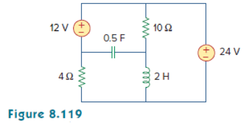
Chapter 8, Problem 75P
Obtain the dual of the circuit in Fig. 8.119.
Expert Solution & Answer
Want to see the full answer?
Check out a sample textbook solution
Students have asked these similar questions
1. Consider the following a unity feedback control system.
R(s) +
E(s)
500(s+2)(s+5)(s+6)
s(s+8)(s+10)(s+12)
-Y(s)
Find the followings:
a) Type of the system
b) Static position error constant Kp, Static velocity error constant Ry and Static
acceleration error constant Ka
c) Find the steady-state error of the system for (i) step input 1(t), (ii) ramp input t 1(t),
(iii) parabolic input t² 1(t).
2. Repeat the above problem for the following system.
R(s) + E(s)
500(s + 2)(s + 5)
(s+8)(s+ 10)(s+12)
Y(s)
3. Repeat the above problem for the following system.
R(s) +
E(s) 500(s+2)(s+4)(s+5)(s+6)(s+7)
s²(s+8)(s+10)(s+12)
Y(s)
4. Consider a unity (negative) feedback control system whose open-loop transfer
function is given by the following.
2
G(s) =
s³ (s + 2)
Find the steady-state error of the system for each of the following inputs.
=
a) u(t) (t²+8t+5) 1(t)
b) u(t) = 3t³ 1(t)
c) u(t) (t+5t² - 1) 1(t)
=
1
2. For the following closed-loop system, G(s) =
and H(s) = ½
(s+4)(s+6)
a. Please draw the root locus by hand and mark the root locus with arrows. Calculate the origin
and angle for asymptotes.
b. Use Matlab to draw the root locus to verify your sketch.
Input
R(s)
Output
C(s)
KG(s)
H(s)
Chapter 8 Solutions
Fundamentals of Electric Circuits
Ch. 8.2 - The switch in Fig. 8.4 was open for a long time...Ch. 8.2 - For the circuit in Fig. 8.7, find: (a) iL(0+),...Ch. 8.3 - If R = 10 , L = 5 H, and C = 2 mF in Fig. 8.8,...Ch. 8.3 - The circuit in Fig. 8.12 has reached steady state...Ch. 8.4 - In Fig. 8.13, let R = 2 , L = 0.4 H, C = 25 mF,...Ch. 8.4 - Refer to the circuit in Fig. 8.17. Find v(t) for t...Ch. 8.5 - Having been in position a for a long time, the...Ch. 8.6 - Find i(t) and v(t) for t 0 in the circuit of Fig....Ch. 8.7 - Determine v and i for t 0 in the circuit of Fig....Ch. 8.7 - For t 0, obtain v0(t) in the circuit of Fig....
Ch. 8.8 - In the op amp circuit shown in Fig. 8.34, vs =...Ch. 8.9 - Find i(t) using PSpice for 0 t 4 s if the pulse...Ch. 8.9 - Refer to the circuit in Fig. 8.21 (see Practice...Ch. 8.10 - Draw the dual circuit of the one in Fig. 8.46.Ch. 8.10 - For the circuit in Fig. 8.50, obtain the dual...Ch. 8.11 - In Fig. 8.52, find the capacitor voltage vC for t ...Ch. 8.11 - The output of a D/A converter is shown in Fig....Ch. 8 - For the circuit in Fig. 8.58, the capacitor...Ch. 8 - For Review Questions 8.1 and 8.2. 8.2For the...Ch. 8 - When a step input is applied to a second-order...Ch. 8 - If the roots of the characteristic equation of an...Ch. 8 - In a series RLC circuit, setting R = 0 will...Ch. 8 - Prob. 6RQCh. 8 - Refer to the series RLC circuit in Fig. 8.59. What...Ch. 8 - Consider the parallel RLC circuit in Fig. 8.60....Ch. 8 - Match the circuits in Fig. 8.61 with the following...Ch. 8 - Prob. 10RQCh. 8 - For the circuit in Fig. 8.62, find: (a)i(0+) and...Ch. 8 - Using Fig. 8.63, design a problem to help other...Ch. 8 - Refer to the circuit shown in Fig. 8.64....Ch. 8 - In the circuit of Fig. 8.65, find: (a) v(0+) and...Ch. 8 - Refer to the circuit in Fig. 8.66. Determine: (a)...Ch. 8 - In the circuit of Fig. 8.67, find: (a) vR(0+) and...Ch. 8 - A series RLC circuit has R = 20 k, L = 0.2 mH, and...Ch. 8 - Design a problem to help other students better...Ch. 8 - The current in an RLC circuit is described by...Ch. 8 - The differential equation that describes the...Ch. 8 - Prob. 11PCh. 8 - If R = 50 , L = 1.5 H, what value of C will make...Ch. 8 - For the circuit in Fig. 8.68, calculate the value...Ch. 8 - The switch in Fig. 8.69 moves from position A to...Ch. 8 - The responses of a series RLC circuit are...Ch. 8 - Find i(t) for t 0 in the circuit of Fig. 8.70....Ch. 8 - In the circuit of Fig. 8.71, the switch...Ch. 8 - Find the voltage across the capacitor as a...Ch. 8 - Obtain v(t) for t 0 in the circuit of Fig. 8.73....Ch. 8 - The switch in the circuit of Fig. 8.74 has been...Ch. 8 - Calculate v(t) for t 0 in the circuit of Fig....Ch. 8 - Assuming R = 2 k, design a parallel RLC circuit...Ch. 8 - For the network in Fig. 8.76, what value of C is...Ch. 8 - The switch in Fig. 8.77 moves from position A to...Ch. 8 - Using Fig. 8.78, design a problem to help other...Ch. 8 - The step response of an RLC circuit is given by...Ch. 8 - Prob. 27PCh. 8 - A series RLC circuit is described by...Ch. 8 - Solve the following differential equations subject...Ch. 8 - Prob. 30PCh. 8 - Consider the circuit in Fig. 8.79. Find vL(0+) and...Ch. 8 - For the circuit in Fig. 8.80, find v(t) for t 0.Ch. 8 - Find v(t) for t 0 in the circuit of Fig. 8.81.Ch. 8 - Calculate i(t) for t 0 in the circuit of Fig....Ch. 8 - Using Fig. 8.83, design a problem to help other...Ch. 8 - Obtain v(t) and i(t) for t 0 in the circuit of...Ch. 8 - For the network in Fig. 8.85, solve for i(t) for t...Ch. 8 - Refer to the circuit in Fig. 8.86. Calculate i(t)...Ch. 8 - Determine v(t) for t 0 in the circuit of Fig....Ch. 8 - The switch in the circuit of Fig. 8.88 is moved...Ch. 8 - For the network in Fig. 8.89, find i(t) for t 0....Ch. 8 - Given the network in Fig. 8.90, find v(t) for t ...Ch. 8 - The switch in Fig. 8.91 is opened at t = 0 after...Ch. 8 - A series RLC circuit has the following parameters:...Ch. 8 - In the circuit of Fig. 8.92, find v(t) and i(t)...Ch. 8 - Prob. 46PCh. 8 - Find the output voltage vo(t) in the circuit of...Ch. 8 - Given the circuit in Fig. 8.95, find i(t) and v(t)...Ch. 8 - Determine i(t) for t 0 in the circuit of Fig....Ch. 8 - For the circuit in Fig. 8.97, find i(t) for t 0....Ch. 8 - Find v(t) for t 0 in the circuit of Fig. 8.98....Ch. 8 - The step response of a parallel RLC circuit is...Ch. 8 - After being open for a day, the switch in the...Ch. 8 - Using Fig. 8.100, design a problem to help other...Ch. 8 - For the circuit in Fig. 8.101, find v(t) for t 0....Ch. 8 - In the circuit of Fig. 8.102, find i(t) for t 0....Ch. 8 - Given the circuit shown in Fig. 8.103, determine...Ch. 8 - In the circuit of Fig. 8.104, the switch has been...Ch. 8 - The switch in Fig. 8.105 has been in position 1...Ch. 8 - Obtain i1 and i2 for t 0 in the circuit of Fig....Ch. 8 - For the circuit in Prob. 8.5, find i and v for t ...Ch. 8 - Find the response vR(t) for t 0 in the circuit of...Ch. 8 - For the op amp circuit in Fig. 8.108, find the...Ch. 8 - Using Fig. 8.109, design a problem to help other...Ch. 8 - Determine the differential equation for the op amp...Ch. 8 - Obtain the differential equations for vo(t) in the...Ch. 8 - In the op amp circuit of Fig. 8.112, determine...Ch. 8 - For the step function vs = u(t), use PSpice or...Ch. 8 - Given the source-free circuit in Fig. 8.114, use...Ch. 8 - For the circuit in Fig. 8.115, use PSpice or...Ch. 8 - Obtain v(t) for 0 t 4 s in the circuit of Fig....Ch. 8 - The switch in Fig. 8.117 has been in position 1...Ch. 8 - Design a problem, to be solved using PSpice or...Ch. 8 - Draw the dual of the circuit shown in Fig. 8.118.Ch. 8 - Obtain the dual of the circuit in Fig. 8.119.Ch. 8 - Find the dual of the circuii in Fig. 8.120.Ch. 8 - Draw the dual of the circuit in Fig. 8.121.Ch. 8 - An automobile airbag igniter is modeled by the...Ch. 8 - A load is modeled as a 100-mH inductor in parallel...Ch. 8 - A mechanical system is modeled by a series RLC...Ch. 8 - An oscillogram can be adequately modeled by a...Ch. 8 - The circuit in Fig. 8.123 is the electrical analog...Ch. 8 - Figure 8.124 shows a typical tunnel-diode...
Knowledge Booster


Learn more about
Need a deep-dive on the concept behind this application? Look no further. Learn more about this topic, electrical-engineering and related others by exploring similar questions and additional content below.Similar questions
- 5. Consider following feedback system. R(s) + 100 S+4 +1 Find the steady-state error for (i) step input and (ii) ramp input.arrow_forward6. Find (i) settling time (Ts), (ii) rise time (Tr), (iii) peak time (Tp), and (iv) percent overshoot (% OS) for each of the following systems whose transfer functions are given by: a) H(s) = 5 s²+12s+20 5 b) H(s) = s²+6s+25 c) H(s) = (s+2) (s²+12s+20) (s²+4s+13) Use dominant pole approximation if needed.arrow_forward7. Answer the following questions. Take help from ChatGPT to answer these questions (if you need). But write the answers briefly using your own words with no more than two sentences and make sure you check whether ChatGPT is giving you the appropriate answers in the context of class. a) Why do we need transient performance metrics? Name a few of such metrics. b) Define (i) settling time, (ii) rise time, (iii) peak time and (iv) percent overshoot. c) What is damping ratio? How does overshoot change with the change of damping ratio? When do we have zero overshoot? d) What is the criterion for selecting dominant pole in higher order systems? When dominant pole approximation is not valid? How will you calculate the transient performance metrics for the case when dominant pole approximation does not hold?arrow_forward
- The transformer rating is 1200:2400 V @ 120 kVA. What is the apparent power provided by the source? What does this mean for the operation of the transformer? Draw the power triangle at the source and calculate the power factor. The magnitude of the voltage source is given in VRMS.arrow_forwardDon't use ai to answer i will report your answerarrow_forwarda) Find the Real and Imaginary Voltage across the inductor to 3 decimal points. b) Find the current and phase angle (phasor) magnitude from the Vs source to 3 decimal points. c) Find the magnitude and phase angle of the complex power(phasor) delivered by the Vs source to 3 decimal points.arrow_forward
- Consider the circuit diagram below. If four identical capacitors, each with a capacitance of 0.07 F, are used to smooth the output, what will the ripple voltage VR be? The diode forward bias voltage, VF, is found to be 0.5 V. Note that the amplitude of v(t) is given in VRMS.arrow_forwarda) Find the complex power absorbed by the -j3 ohm capacitor to 3 decimal points.b) Find the complex power absorbed by the 4 ohm resistor to 3 decimal pointsc) Find the complex power absorbed by the j5 ohm inductor to 3 decimal points.arrow_forwardI am looking for schematic ideas or recommendations for designing the required step-down system. Since the input is a 600V DC supply, a DC-DC converter may be necessary, as transformers are typically used for AC voltage. Key considerations would include: Voltage regulation: Ensuring a stable and consistent 120V DC output.Component selection: Choosing appropriate DC-DC converter modules, capacitors for filtering, and protective components such as fuses or circuit breakers.Lighting system: Recommendations on energy-efficient lighting options like LEDs, which work well with DC power and offer durability for railway applications.Thermal management: Addressing heat dissipation within the converter and lighting circuit.Safety and standards: Complying with safety regulations for electrical systems in railways. I would greatly appreciate detailed insights into the design process, including key circuit components and configurations, as well as any schematic diagrams or references.arrow_forward
- 1 2. For the following closed-loop system, G(s) = and H(s) = ½ (s+4)(s+6) a. Please draw the root locus by hand and mark the root locus with arrows. Calculate the origin and angle for asymptotes. b. Use Matlab to draw the root locus to verify your sketch. Input R(s) Output C(s) KG(s) H(s)arrow_forward1. In the following unity feedback system, we have G(s) = R(s) + K(s + 1) s(s + 2)(s +5) G(s) C(s) use Routh-Hurwitz stability criterion to find the range of K for the stability of the system.arrow_forwardWhat is the current flowing through the load resistor, RL (in ARMS)? How much power does the voltage source, V1, provide to the circuit? The magnitude of V1 is given in VRMS.arrow_forward
arrow_back_ios
SEE MORE QUESTIONS
arrow_forward_ios
Recommended textbooks for you
 Introductory Circuit Analysis (13th Edition)Electrical EngineeringISBN:9780133923605Author:Robert L. BoylestadPublisher:PEARSON
 Delmar's Standard Textbook Of ElectricityElectrical EngineeringISBN:9781337900348Author:Stephen L. HermanPublisher:Cengage Learning
 Programmable Logic ControllersElectrical EngineeringISBN:9780073373843Author:Frank D. PetruzellaPublisher:McGraw-Hill Education
 Fundamentals of Electric CircuitsElectrical EngineeringISBN:9780078028229Author:Charles K Alexander, Matthew SadikuPublisher:McGraw-Hill Education
 Electric Circuits. (11th Edition)Electrical EngineeringISBN:9780134746968Author:James W. Nilsson, Susan RiedelPublisher:PEARSON
 Engineering ElectromagneticsElectrical EngineeringISBN:9780078028151Author:Hayt, William H. (william Hart), Jr, BUCK, John A.Publisher:Mcgraw-hill Education,
Introductory Circuit Analysis (13th Edition)
Electrical Engineering
ISBN:9780133923605
Author:Robert L. Boylestad
Publisher:PEARSON
Delmar's Standard Textbook Of Electricity
Electrical Engineering
ISBN:9781337900348
Author:Stephen L. Herman
Publisher:Cengage Learning
Programmable Logic Controllers
Electrical Engineering
ISBN:9780073373843
Author:Frank D. Petruzella
Publisher:McGraw-Hill Education
Fundamentals of Electric Circuits
Electrical Engineering
ISBN:9780078028229
Author:Charles K Alexander, Matthew Sadiku
Publisher:McGraw-Hill Education
Electric Circuits. (11th Edition)
Electrical Engineering
ISBN:9780134746968
Author:James W. Nilsson, Susan Riedel
Publisher:PEARSON
Engineering Electromagnetics
Electrical Engineering
ISBN:9780078028151
Author:Hayt, William H. (william Hart), Jr, BUCK, John A.
Publisher:Mcgraw-hill Education,
Systems and Simulation - Lecture 3: Modelling of Mechanical systems; Author: bioMechatronics Lab;https://www.youtube.com/watch?v=fMcDdyoC9mA;License: Standard Youtube License