
Fundamentals of Electric Circuits
6th Edition
ISBN: 9780078028229
Author: Charles K Alexander, Matthew Sadiku
Publisher: McGraw-Hill Education
expand_more
expand_more
format_list_bulleted
Videos
Textbook Question
Chapter 8, Problem 3P
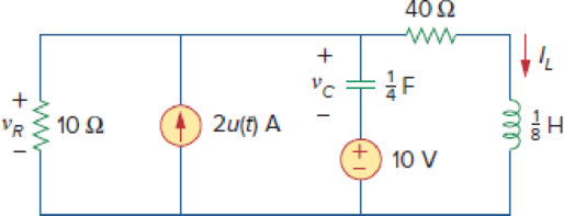
Refer to the circuit shown in Fig. 8.64. Calculate:
- (a) iL(0+), vC(0+), and vR(0+),
- (b) diL(0+)/dt, dvC(0+)/dt, and dvR(0+)/dt,
- (c) iL(∞), vC(∞), and vR(∞).
Figure 8.64
Expert Solution & Answer
Want to see the full answer?
Check out a sample textbook solution
Students have asked these similar questions
z+4
What is the value of √cz²+2z+5 dz
Sc
a) If C is the circle |z|=1.
c) If C is the circle |z+1+i|=2.
b) If C is the circle |z+1-i|=2.
z+1
What is the value of
Sc
73.
C -2z²
3-zzz dz
i)
ii)
iii)
If C is the circle |z|=1.
If C is the circle |z-2-i|=2.
If C is the circle |z-1-2i|=2.
Application of Complex Inversion Integral for Inverse Z-transform
Find Z-1 {(2-1)(2+2)}
Chapter 8 Solutions
Fundamentals of Electric Circuits
Ch. 8.2 - The switch in Fig. 8.4 was open for a long time...Ch. 8.2 - For the circuit in Fig. 8.7, find: (a) iL(0+),...Ch. 8.3 - If R = 10 , L = 5 H, and C = 2 mF in Fig. 8.8,...Ch. 8.3 - The circuit in Fig. 8.12 has reached steady state...Ch. 8.4 - In Fig. 8.13, let R = 2 , L = 0.4 H, C = 25 mF,...Ch. 8.4 - Refer to the circuit in Fig. 8.17. Find v(t) for t...Ch. 8.5 - Having been in position a for a long time, the...Ch. 8.6 - Find i(t) and v(t) for t 0 in the circuit of Fig....Ch. 8.7 - Determine v and i for t 0 in the circuit of Fig....Ch. 8.7 - For t 0, obtain v0(t) in the circuit of Fig....
Ch. 8.8 - In the op amp circuit shown in Fig. 8.34, vs =...Ch. 8.9 - Find i(t) using PSpice for 0 t 4 s if the pulse...Ch. 8.9 - Refer to the circuit in Fig. 8.21 (see Practice...Ch. 8.10 - Draw the dual circuit of the one in Fig. 8.46.Ch. 8.10 - For the circuit in Fig. 8.50, obtain the dual...Ch. 8.11 - In Fig. 8.52, find the capacitor voltage vC for t ...Ch. 8.11 - The output of a D/A converter is shown in Fig....Ch. 8 - For the circuit in Fig. 8.58, the capacitor...Ch. 8 - For Review Questions 8.1 and 8.2. 8.2For the...Ch. 8 - When a step input is applied to a second-order...Ch. 8 - If the roots of the characteristic equation of an...Ch. 8 - In a series RLC circuit, setting R = 0 will...Ch. 8 - Prob. 6RQCh. 8 - Refer to the series RLC circuit in Fig. 8.59. What...Ch. 8 - Consider the parallel RLC circuit in Fig. 8.60....Ch. 8 - Match the circuits in Fig. 8.61 with the following...Ch. 8 - Prob. 10RQCh. 8 - For the circuit in Fig. 8.62, find: (a)i(0+) and...Ch. 8 - Using Fig. 8.63, design a problem to help other...Ch. 8 - Refer to the circuit shown in Fig. 8.64....Ch. 8 - In the circuit of Fig. 8.65, find: (a) v(0+) and...Ch. 8 - Refer to the circuit in Fig. 8.66. Determine: (a)...Ch. 8 - In the circuit of Fig. 8.67, find: (a) vR(0+) and...Ch. 8 - A series RLC circuit has R = 20 k, L = 0.2 mH, and...Ch. 8 - Design a problem to help other students better...Ch. 8 - The current in an RLC circuit is described by...Ch. 8 - The differential equation that describes the...Ch. 8 - Prob. 11PCh. 8 - If R = 50 , L = 1.5 H, what value of C will make...Ch. 8 - For the circuit in Fig. 8.68, calculate the value...Ch. 8 - The switch in Fig. 8.69 moves from position A to...Ch. 8 - The responses of a series RLC circuit are...Ch. 8 - Find i(t) for t 0 in the circuit of Fig. 8.70....Ch. 8 - In the circuit of Fig. 8.71, the switch...Ch. 8 - Find the voltage across the capacitor as a...Ch. 8 - Obtain v(t) for t 0 in the circuit of Fig. 8.73....Ch. 8 - The switch in the circuit of Fig. 8.74 has been...Ch. 8 - Calculate v(t) for t 0 in the circuit of Fig....Ch. 8 - Assuming R = 2 k, design a parallel RLC circuit...Ch. 8 - For the network in Fig. 8.76, what value of C is...Ch. 8 - The switch in Fig. 8.77 moves from position A to...Ch. 8 - Using Fig. 8.78, design a problem to help other...Ch. 8 - The step response of an RLC circuit is given by...Ch. 8 - Prob. 27PCh. 8 - A series RLC circuit is described by...Ch. 8 - Solve the following differential equations subject...Ch. 8 - Prob. 30PCh. 8 - Consider the circuit in Fig. 8.79. Find vL(0+) and...Ch. 8 - For the circuit in Fig. 8.80, find v(t) for t 0.Ch. 8 - Find v(t) for t 0 in the circuit of Fig. 8.81.Ch. 8 - Calculate i(t) for t 0 in the circuit of Fig....Ch. 8 - Using Fig. 8.83, design a problem to help other...Ch. 8 - Obtain v(t) and i(t) for t 0 in the circuit of...Ch. 8 - For the network in Fig. 8.85, solve for i(t) for t...Ch. 8 - Refer to the circuit in Fig. 8.86. Calculate i(t)...Ch. 8 - Determine v(t) for t 0 in the circuit of Fig....Ch. 8 - The switch in the circuit of Fig. 8.88 is moved...Ch. 8 - For the network in Fig. 8.89, find i(t) for t 0....Ch. 8 - Given the network in Fig. 8.90, find v(t) for t ...Ch. 8 - The switch in Fig. 8.91 is opened at t = 0 after...Ch. 8 - A series RLC circuit has the following parameters:...Ch. 8 - In the circuit of Fig. 8.92, find v(t) and i(t)...Ch. 8 - Prob. 46PCh. 8 - Find the output voltage vo(t) in the circuit of...Ch. 8 - Given the circuit in Fig. 8.95, find i(t) and v(t)...Ch. 8 - Determine i(t) for t 0 in the circuit of Fig....Ch. 8 - For the circuit in Fig. 8.97, find i(t) for t 0....Ch. 8 - Find v(t) for t 0 in the circuit of Fig. 8.98....Ch. 8 - The step response of a parallel RLC circuit is...Ch. 8 - After being open for a day, the switch in the...Ch. 8 - Using Fig. 8.100, design a problem to help other...Ch. 8 - For the circuit in Fig. 8.101, find v(t) for t 0....Ch. 8 - In the circuit of Fig. 8.102, find i(t) for t 0....Ch. 8 - Given the circuit shown in Fig. 8.103, determine...Ch. 8 - In the circuit of Fig. 8.104, the switch has been...Ch. 8 - The switch in Fig. 8.105 has been in position 1...Ch. 8 - Obtain i1 and i2 for t 0 in the circuit of Fig....Ch. 8 - For the circuit in Prob. 8.5, find i and v for t ...Ch. 8 - Find the response vR(t) for t 0 in the circuit of...Ch. 8 - For the op amp circuit in Fig. 8.108, find the...Ch. 8 - Using Fig. 8.109, design a problem to help other...Ch. 8 - Determine the differential equation for the op amp...Ch. 8 - Obtain the differential equations for vo(t) in the...Ch. 8 - In the op amp circuit of Fig. 8.112, determine...Ch. 8 - For the step function vs = u(t), use PSpice or...Ch. 8 - Given the source-free circuit in Fig. 8.114, use...Ch. 8 - For the circuit in Fig. 8.115, use PSpice or...Ch. 8 - Obtain v(t) for 0 t 4 s in the circuit of Fig....Ch. 8 - The switch in Fig. 8.117 has been in position 1...Ch. 8 - Design a problem, to be solved using PSpice or...Ch. 8 - Draw the dual of the circuit shown in Fig. 8.118.Ch. 8 - Obtain the dual of the circuit in Fig. 8.119.Ch. 8 - Find the dual of the circuii in Fig. 8.120.Ch. 8 - Draw the dual of the circuit in Fig. 8.121.Ch. 8 - An automobile airbag igniter is modeled by the...Ch. 8 - A load is modeled as a 100-mH inductor in parallel...Ch. 8 - A mechanical system is modeled by a series RLC...Ch. 8 - An oscillogram can be adequately modeled by a...Ch. 8 - The circuit in Fig. 8.123 is the electrical analog...Ch. 8 - Figure 8.124 shows a typical tunnel-diode...
Knowledge Booster


Learn more about
Need a deep-dive on the concept behind this application? Look no further. Learn more about this topic, electrical-engineering and related others by exploring similar questions and additional content below.Similar questions
- 4z Find the residue of f(z) = (z-3)(z+1)²arrow_forwardwhat is the integral of f(z): -3z+4 = around the circle z(z-1)(z-2) |z|=3/2?arrow_forward1. The communication channel bandwidth uses is 25 MHz centered at 1GHz and uses BPSK. The noise power spectral density of the channel is 10^-9 W/Hz. The channel loss between the transmitter and receiver is 25dB. The application requires a BER of less than 10^-4. Determine the minimum transmit power required.arrow_forward
- 4. A differential BPSK transmitter consumes 10 W and provides a BER of 1*10^-7. If the system moves to 16-QAM, what is new minimum transmit power?arrow_forward5. The noise power (in watts) measured in a 40MHz Wifi channel is 230*10^-6 Watts. The access point (AP) output power is 600 mW and only uses 256QAM and has a data rate of 400Mbps. The channel losses can be modeled as 0.4dB/meter. An application on your phone requires a BER of < than 1*10^-4. A) What is the maximum distance between the AP and your phone? b) if the AP and my phone could switch to 64QAM and support the same data rate, what is the new maximum distance between the AP and my phone?arrow_forward3. You are to design a 9-volt battery operated communication system that has a center frequency of 2.4 GHz. It must last 10 years without replacing batteries. The application requires a BER of <10^-5 and a data rate of 500bps. The channel can be modeled as AWGN with a noise power spectral density of 10^- 8 W/Hz. (a) What modulation scheme would you use? B) what is the required capacity of the batteries? and (c) Is the battery commercially available?arrow_forward
- Refer to the logic diagram of Figure. Gate 1 and gate 4 belong to the standard TTL family, while gate 2 and gate 3 belong to the Schottky TTL family and the low-power Schottky TTL family respectively. Determine whether the fan-out capability of gate 1 is being exceeded. Relevant data for the three logic families are given in Table 3(a).arrow_forward2. An existing system uses noncoherent BASK. The application requires a BER of <10^-5. The current transmit power is 25 Watts. If the system changes to a coherent BPSK modulation scheme, what is the new transmit power required to deliver the same BER?arrow_forwardfunctions: where are the Cauchy-Riemann equations satisfied by the 1- w = z² - 4 2- w = 7 Z Z+5 3- w = Z-2 z+1arrow_forward
- Find the integral for ezz Cz-i ezz Zdz and $c (z-i)³ dzarrow_forwardDetermine the voltage across A and B in the circuit given below:arrow_forwardAn inductive coil having negligible resistance and 0.1H inductance is connected a supply of 220V, 50 Hz. Calculate (a) Inductive reactance, (b) RMS value of Current, (c) Power consumed, (d) Power factor, (e) Write down the equations for voltage and current.arrow_forward
arrow_back_ios
SEE MORE QUESTIONS
arrow_forward_ios
Recommended textbooks for you
 Introductory Circuit Analysis (13th Edition)Electrical EngineeringISBN:9780133923605Author:Robert L. BoylestadPublisher:PEARSON
 Delmar's Standard Textbook Of ElectricityElectrical EngineeringISBN:9781337900348Author:Stephen L. HermanPublisher:Cengage Learning
 Programmable Logic ControllersElectrical EngineeringISBN:9780073373843Author:Frank D. PetruzellaPublisher:McGraw-Hill Education
 Fundamentals of Electric CircuitsElectrical EngineeringISBN:9780078028229Author:Charles K Alexander, Matthew SadikuPublisher:McGraw-Hill Education
 Electric Circuits. (11th Edition)Electrical EngineeringISBN:9780134746968Author:James W. Nilsson, Susan RiedelPublisher:PEARSON
 Engineering ElectromagneticsElectrical EngineeringISBN:9780078028151Author:Hayt, William H. (william Hart), Jr, BUCK, John A.Publisher:Mcgraw-hill Education,
Introductory Circuit Analysis (13th Edition)
Electrical Engineering
ISBN:9780133923605
Author:Robert L. Boylestad
Publisher:PEARSON
Delmar's Standard Textbook Of Electricity
Electrical Engineering
ISBN:9781337900348
Author:Stephen L. Herman
Publisher:Cengage Learning
Programmable Logic Controllers
Electrical Engineering
ISBN:9780073373843
Author:Frank D. Petruzella
Publisher:McGraw-Hill Education
Fundamentals of Electric Circuits
Electrical Engineering
ISBN:9780078028229
Author:Charles K Alexander, Matthew Sadiku
Publisher:McGraw-Hill Education
Electric Circuits. (11th Edition)
Electrical Engineering
ISBN:9780134746968
Author:James W. Nilsson, Susan Riedel
Publisher:PEARSON
Engineering Electromagnetics
Electrical Engineering
ISBN:9780078028151
Author:Hayt, William H. (william Hart), Jr, BUCK, John A.
Publisher:Mcgraw-hill Education,
L21E127 Control Systems Lecture 21 Exercise 127: State-space model of an electric circuit; Author: bioMechatronics Lab;https://www.youtube.com/watch?v=sL0LtyfNYkM;License: Standard Youtube License