
Videos
In the circuit of Fig. 8.92, find v(t) and i(t) for t > 0.
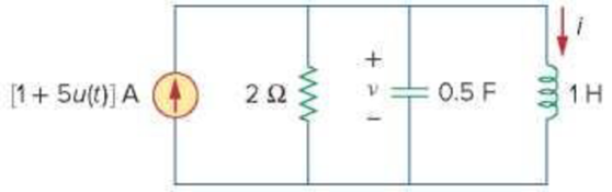
Figure 8.92
For Prob. 8.45.
Find the expression of voltage
Answer to Problem 45P
For
Explanation of Solution
Given data:
Refer to Figure 8.92 in the textbook.
Formula used:
Write an expression to calculate the neper frequency for parallel
Here,
Write an expression to calculate the natural frequency for parallel
Here,
The three types of responses for a series
- i. When
- ii. When
- iii. When
Write a general expression for the step response of a parallel
Here,
Write an expression to calculate the damped natural frequency.
Write an expression to calculate the value of step input.
Calculation:
The given circuit is redrawn as shown in Figure 1.
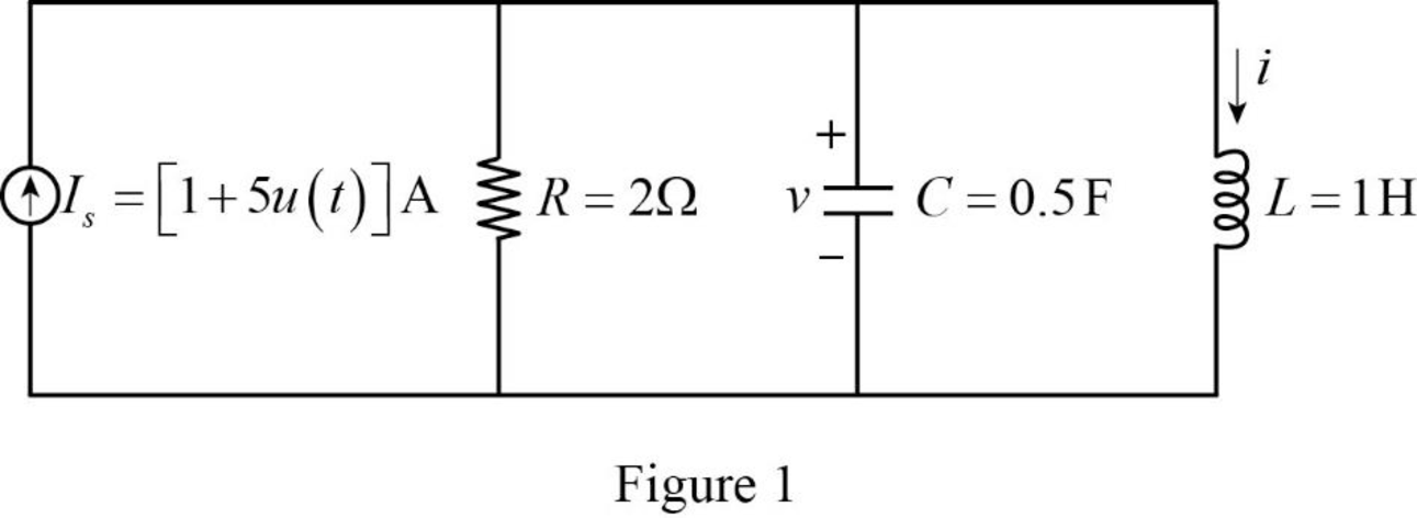
For a DC circuit at steady state condition when time
The value of current source is calculated as follows for
Now the Figure 1 is reduced as shown in Figure 2.
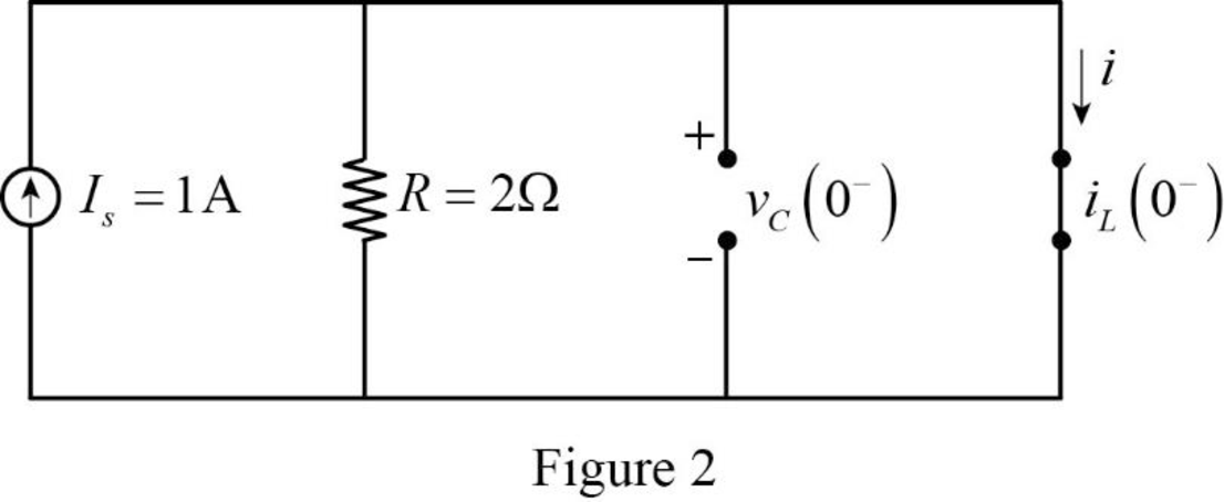
Refer to Figure 2, the circuit is short circuited and full current flows through the inductor.
Refer to Figure 2, the short circuited inductor and open circuited capacitor are connected in parallel. Since the full current flows through the short circuit path there is no voltage across the capacitor.
The current through inductor and voltage across capacitor is always continuous so that,
For
Now, the Figure 1 is reduced as shown in Figure 3.
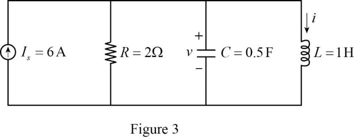
Refer to Figure 3, the circuit shows the step response of a parallel
Substitute
Substitute
Comparing the value of neper and natural frequency, the value of neper frequency is greater than the natural frequency
Substitute
Substitute
Substitute
Substitute
Simplify the above equation to find
Substitute
Differentiate equation (7) with respect to
Substitute
For the parallel
Write an expression to calculate the voltage across the inductor.
Rearrange equation (10) to find
Substitute
Substitute
Substitute
Substitute
Simplify the above equation to find
Substitute
Substitute
Substitute
Substitute
Conclusion:
Thus, the expression of voltage
Want to see more full solutions like this?
Chapter 8 Solutions
Fundamentals of Electric Circuits


- Can you help me find the result of an integral 0/2 a² X + a dxarrow_forwardQ1/Sketch the root locus for the system shown in Figure 1 and find the following: a. The exact point and gain where the locus crosses the jo-axis b. The breakaway point on the real axis c. The range of K within which the system is stable d. Angles of departure and arrival R(s) + K(s²-4s +20) C(s) (s+2)(s + 4)arrow_forwardExam2 Subject: (Numerical Analysis) Class: Third Date: 27/4/2025 Time: 60 minutes Q1. For what values of k does this system of equations has no solution? (use Gauss-Jordan eliminations) kx + y + z = 1 x+ky + z = 1 x+y+kz=1arrow_forward
- Consider the Difference equation of a causal Linear time-invariant (LTI) system given by: (y(n) - 1.5y(n - 1) + 0.5y(n = 2) = x(n) a) Implement the difference equation model of this system. b) Find the system transfer function H(z). c) For an input x(n) = 8(n), determine the output response y(n). d) Verify the initial value theorem y(0) with part (c).arrow_forwardQ5B. Find the type of the controller in the following figures and use real values to find the transfer function of three of them[ Hint Pi,Pd and Lead,lag are found so put the controller with its corresponding compensator]. R₁ R₂ Rz HE C2 RA HE R₁ R2 RA とarrow_forwardQ1// Sketch the root locus for the unity feedback system. Where G(s)=)= K S3+252 +25 and find the following a. Sketch the asymptotes b. The exact point and gain where the locus crosses the jo-axis c. The breakaway point on the real axis d. The range of K within which the system is stable e. Angles of departure and arrival.arrow_forward
- Determine X(w) for the given function shown in Figure (1) by applying the differentiation property of the Fourier Transform. Figure (1) -1 x(t)arrow_forwardCan you solve a question with a drawing Determine X(w) for the given function shown in Figure (1) by applying the differentiation property of the Fourier Transform. Figure (1) -1 x(t)arrow_forwardAn inductor has a current flow of 3 A when connected to a 240 V, 60 Hz power line. The inductor has a wire resistance of 15 Find the Q of the inductorarrow_forward
- صورة من s94850121arrow_forwardThe joint density function of two continuous random variables X and Yis: p(x, y) = {Keós (x + y) Find (i) the constant K 0 2 0arrow_forwardShow all the steps please, Solve for the current through R2 if E2 is replaced by a current source of 10mA using superposition theorem. R5=470Ω R2=1000Ω R6=820Ωarrow_forwardarrow_back_iosSEE MORE QUESTIONSarrow_forward_ios
 Introductory Circuit Analysis (13th Edition)Electrical EngineeringISBN:9780133923605Author:Robert L. BoylestadPublisher:PEARSON
 Delmar's Standard Textbook Of ElectricityElectrical EngineeringISBN:9781337900348Author:Stephen L. HermanPublisher:Cengage Learning
 Programmable Logic ControllersElectrical EngineeringISBN:9780073373843Author:Frank D. PetruzellaPublisher:McGraw-Hill Education
 Fundamentals of Electric CircuitsElectrical EngineeringISBN:9780078028229Author:Charles K Alexander, Matthew SadikuPublisher:McGraw-Hill Education
 Electric Circuits. (11th Edition)Electrical EngineeringISBN:9780134746968Author:James W. Nilsson, Susan RiedelPublisher:PEARSON
 Engineering ElectromagneticsElectrical EngineeringISBN:9780078028151Author:Hayt, William H. (william Hart), Jr, BUCK, John A.Publisher:Mcgraw-hill Education,