
Concept explainers
Draw the influence lines for the force in member AB, BG, DF, and FG.
Explanation of Solution
Calculation:
Find the support reactions.
Apply 1 k moving load from E to G in the top chord member.
Draw the free body diagram of the member as in Figure 1.
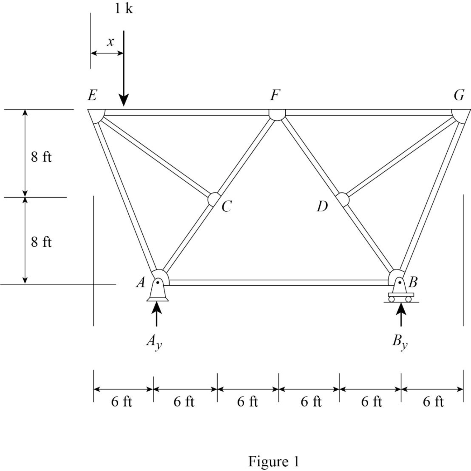
Find the reaction at A and B when 1 k load placed from E to G.
Apply moment equilibrium at A.
Apply force equilibrium equation along vertical.
Consider the upward force as positive
Influence line for the force in member AB.
The expressions for the member force
Draw the free body diagram of member with section aa as shown in Figure 2.
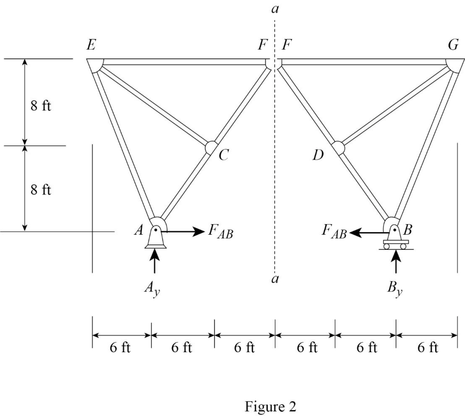
Refer Figure 2.
Find the equation of member force AB.
Apply a 1 k load at just left of F
Consider the right hand portion to section a-a.
Apply moment equilibrium equation at F.
Consider clockwise moment as positive and anticlockwise moment as negative.
Substitute
Apply a 1 k load at just right of F
Consider the left hand portion to section a-a.
Apply moment equilibrium equation at F.
Consider clockwise moment as positive and anticlockwise moment as negative.
Substitute
Thus, the equation of force in the member AB,
Find the force in member AB using the Equation (1) and (2) and then summarize the value in Table 1.
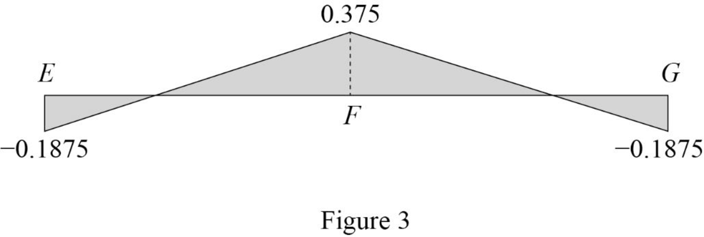
| x (ft) | Apply 1 k load | Force in member AB (k) | Influence line ordinate for the force in member AB (k/k) |
| 0 | E | ||
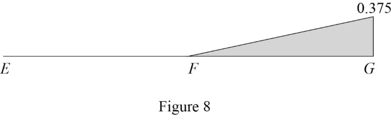
| 18 | F | 0.375 | |
| 36 | G |
Sketch the influence line diagram for ordinate for the force in member AB using Table 2 as shown in Figure 3.
Influence line for the force in member BG.
The expressions for the member force
Draw the free body diagram of section a-a as shown in Figure 4.
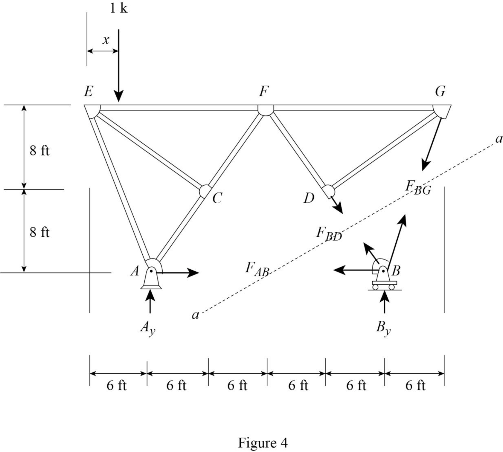
Refer Figure 4.
Find the force in member BG.
Apply 1 k load just left of F
Consider the section EF.
The member force of EF not affected when 1 k load applied from E to F. Therefore, the influence line ordinate of member force BG is 0 k/k from E to F.
Apply a 1 k load just the right of F
Apply moment equilibrium at F.
Consider the section right of line a-a.
Consider clockwise moment as positive and anticlockwise moment as negative.
Substitute
Thus, the equation of force in the member BG,
Find the force in member BG using the Equation (3) and (4) and then summarize the value in Table 2.
| x (ft) | Apply 1 k load | Force in member BG (k) | Influence line ordinate for the force in member BG (k/k) |
| 0 | E | 0 | |
| 18 | F | 0 | |
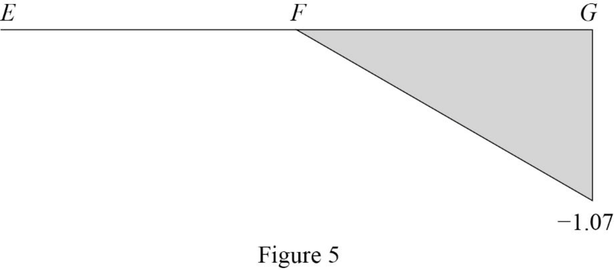
| 36 | G | ‑1.07 |
Sketch the influence line diagram for ordinate for the force in member BG using Table 2 as shown in Figure 5.
Influence line for the force in member DF.
The expressions for the member force
Draw the free body diagram of section a-a as shown in Figure 6.
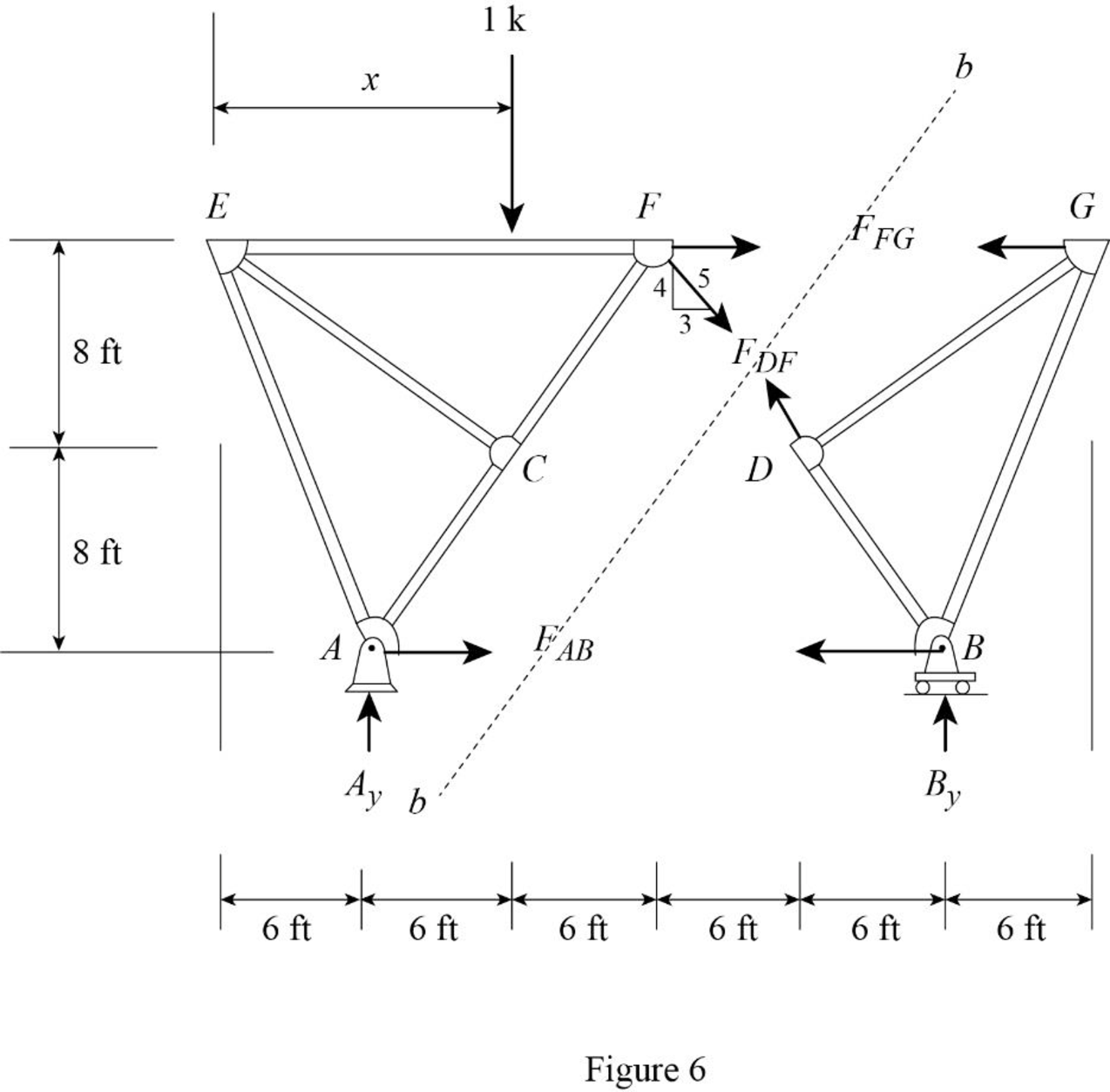
Refer Figure 6.
Find the force in member DF.
Apply 1 k load just left of F
Consider the section right of line bb.
Apply moment equilibrium at G.
Consider clockwise moment as positive and anticlockwise moment as negative.
Substitute
Apply 1 k load just right of F
Consider the section left of line bb.
Apply moment equilibrium at E.
Consider clockwise moment as positive and anticlockwise moment as negative.
Substitute
Thus, the equation of force in the member DF,
Find the force in member DF using the Equation (5) and (6) and then summarize the value in Table 3.
| x (ft) | Apply 1 k load | Force in member DF (k) | Influence line ordinate for the force in member DF (k/k) |
| 0 | E | 0.3125 | |
| 18 | F | ‑0.625 | ‑0.625 |
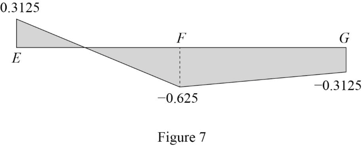
| 36 | G | ‑0.3125 | ‑0.3125 |
Sketch the influence line diagram for ordinate for the force in member DF using Table 3 as shown in Figure 7.
Influence line for the force in member FG.
Refer Figure 6.
Find the force in member FG.
Apply 1 k load just left of F
Consider the section right of line bb.
Apply moment equilibrium at B.
Consider clockwise moment as positive and anticlockwise moment as negative.
Apply 1 k load just right of F
Consider the section left of line bb.
Apply moment equilibrium at A.
Consider clockwise moment as positive and anticlockwise moment as negative.
Substitute
Thus, the equation of force in the member FG,
Find the force in member FG using the Equation (7) and (8) and then summarize the value in Table 4.
| x (ft) | Apply 1 k load | Force in member FG (k) | Influence line ordinate for the force in member FG (k/k) |
| 0 | E | 0.3125 | |
| 18 | F | ‑0.625 | ‑0.625 |
| 36 | G | ‑0.3125 | ‑0.3125 |
Sketch the influence line diagram for ordinate for the force in member FG using Table 4 as shown in Figure 8.
Want to see more full solutions like this?
Chapter 8 Solutions
Structural Analysis


- A trapezoidal drainage ditch along a highway system has a side slope of 2:1 anda bottom width of 8.0 ft. The ditch is to be used to discharge a flow of 500 ft3/sec.If the ditch slope (longitudinal) is 1.0% and the Manning coefficient is 0.02,determine the minimum depth required for the ditch. Is the flow supercritical orsubcritical? Justify your answer.arrow_forwardDetermine the global stiffness matrix of the beam shown in Fig. 3. Assume supports at 1 and 3 are rollers and the support at 2 is a pinned support. Indicate the degrees of freedom in all the stiffness matrices. EI is constant, w=60kN/m, L1=1.25m and L2=3.45marrow_forwardA simply supported beam ten feet long has a 10 Kip load two feet from the left end. What is the maximum moment in the beam? 8 kip-feet 24 kip-feet 16 kip-feet 20 kip-feetarrow_forward
- The moisture content of wood test was performed according to ASTM D4442 procedure and produced the following data:Weight of specimen in the green (moist) condition = 0.70 lbWeight of oven-dry specimen = 0.45.What is the moisture content in percent (%) of the given wood. 64.3 35.7 46.7 55.6arrow_forwardCalculate ALL nodal displacements and ALL the member forces in the truss. Please use the ID's noted in the truss diagramarrow_forwardQ3. In a water flood operation in reservoir A, water is being distributed to severalinjection wells from a common injection system; that is, water is supplied to all thewells at approximately the same well head pressure. Routine measurement of theindividual well injection rates by the team of field operators showed that one well wasreceiving approximately 45% more than its neighbours. The sum of the kh productsfor all of the injection wells were approximately the same depth. As a member of theteam, explain:What are the possible causes of the abnormally high injection rate in this well, andwhat production logs or other tests might be run to further diagnose the problem andplan remedial action?arrow_forward
- Question 1 20 pts Test data on the bending strength of construction wood poles of various diameter are presented below assuming the same length. Kip- 1000 lbf. Using the following data with 2nd order Newton polynomial interpolation, we want to determine the strength of the material for x=4.5 in. Which data point will be used as x? After you found x0, enter the value of x-xo in the solution. Answer shall be in one decimal place. Distance (in) 2.6 1.5 8.3 2.8 5.7 Strength (kips) 100 200 300 400 500arrow_forwardSolve pleasearrow_forwardsolve all of the last names from A-K to please for example use k=100k/in , m =1000lb/g . use el centro (2nd picture ) to solve the questions. Thank you for your help! for the following questions ignore that last name and just solve it pleae: Verify the modes that are orthogonal Normalize the first mode uisng electro with 2%damping, Determine Sa&Sd only for the first modearrow_forward
- For question 2 do 2% please. Use El centro spectrum to answer the secon question please. Thank you for your help!arrow_forwardsolve pleasearrow_forwardA mechanism for pushing small boxes from an assembly line onto a conveyor belt is shown with arm OD and crank CB in their vertical positions. For the configuration shown, crank CB has a constant clockwise angular velocity of 0.6π rad/s. Determine the acceleration QE of E (positive if to the right, negative if down). 450 mm 215 mm 565 mm A 185 mm 105 mm 110185. mm mm Answer: a = i B 40 mm E m/s²arrow_forward