
Concept explainers
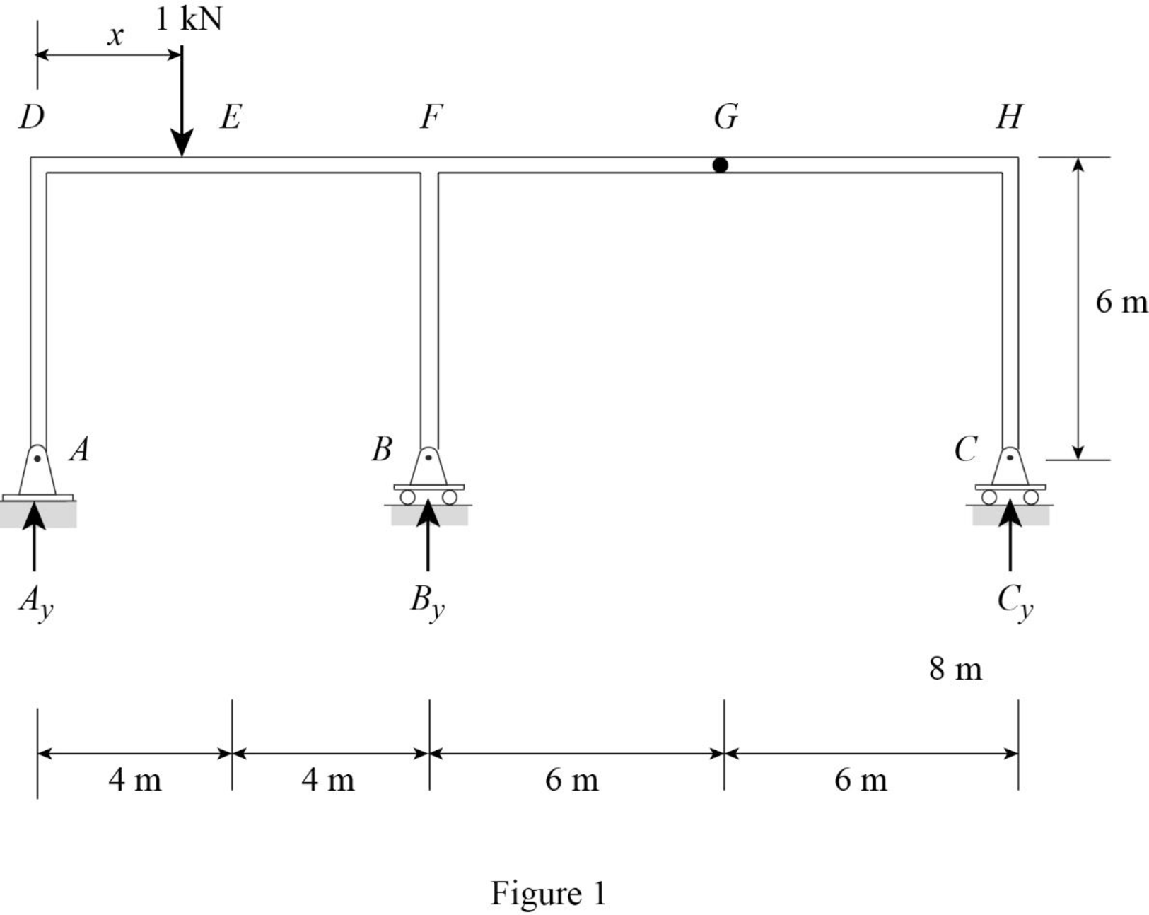
Draw the influence lines for the vertical reactions at supports A, B, C and the shear and bending moment at point E.
Explanation of Solution
Calculation:
Apply a 1 kN unit moving load at a distance of x from left end D.
Sketch the free body diagram of frame as shown in Figure 1.
Influence line for vertical reaction at supports C.
Refer Figure 1.
Find the equation of vertical reaction at supports C.
Apply 1 kN load just left of G
Consider section GH.
Take moment at G from C.
Consider clockwise moment as positive and anticlockwise moment as negative.
Apply 1 kN load just right of G
Consider section GH.
Take moment at G from C.
Consider clockwise moment as positive and anticlockwise moment as negative.
Thus, the equation of vertical reaction at supports C as follows,
Find the influence line ordinate of
Substitute 20 m for
Thus, the influence line ordinate of
Similarly calculate the influence line ordinate of
| x (m) | Points | Influence line ordinate of |
| 0 | D | 0 |
| 4 | E | 0 |
| 8 | F | 0 |
| 14 | G | 0 |
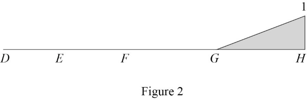
| 20 | H | 1 |
Sketch the influence line diagram for vertical reaction at supports C using Table 1 as shown in Figure 2.
Influence line for vertical reaction at support A.
Apply 1 kN load just left of F
Refer Figure 1.
Find the equation of vertical reaction at supports C.
Consider section DF.
Take moment at B from A.
Consider clockwise moment as positive and anticlockwise moment as negative.
Apply 1 kN load just right of F.
Consider section FH.
Consider moment at B from A is equal to from C.
Consider clockwise moment as positive and anticlockwise moment as negative.
Find the equation of vertical reaction at A from F to G
Substitute 0 for
Find the equation of vertical reaction at A from G to H
Substitute
Thus, the equation of vertical reaction at supports A as follows,
Find the influence line ordinate of
Substitute 14 m for
Thus, the influence line ordinate of
Similarly calculate the influence line ordinate of
| x (m) | Points | Influence line ordinate of |
| 0 | D | 1 |
| 4 | E | 0.5 |
| 8 | F | 0 |
| 14 | G | |
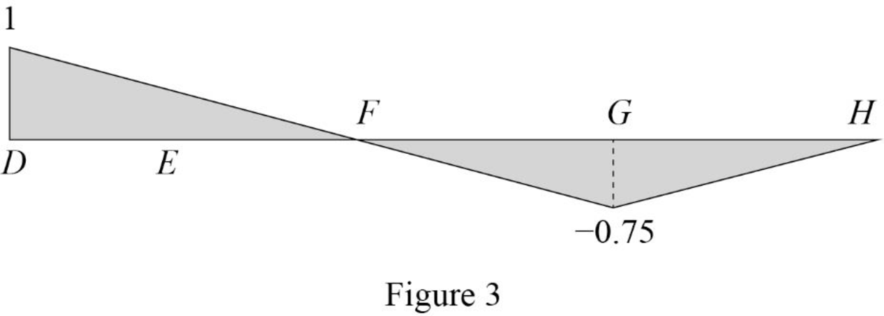
| 20 | H | 0 |
Sketch the influence line diagram for the vertical reaction at support A using Table 2 as shown in Figure 3.
Influence line for vertical reaction at support B.
Apply a 1 kN unit moving load at a distance of x from left end C.
Refer Figure 1.
Apply vertical equilibrium in the system.
Consider upward force as positive and downward force as negative.
Find the equation of vertical support reaction
Substitute
Find the equation of vertical support reaction
Substitute
Thus, the equation of vertical support reaction at B as follows,
Find the influence line ordinate of
Substitute 8 m for
Thus, the influence line ordinate of
Similarly calculate the influence line ordinate of
| x (m) | Points | Influence line ordinate of |
| 0 | D | 0 |
| 4 | E | 0.5 |
| 8 | F | 1 |
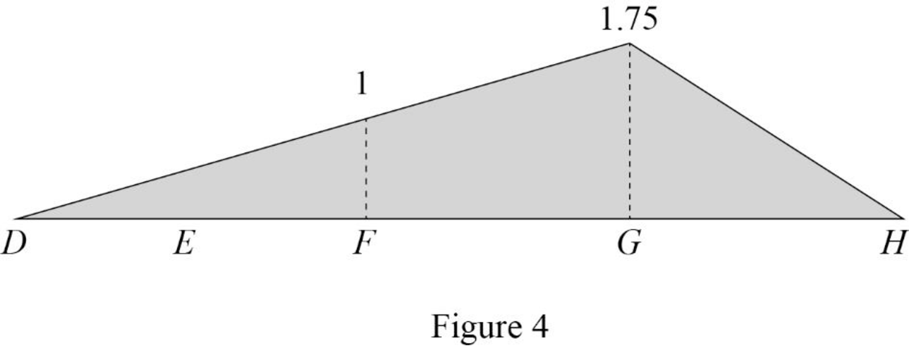
| 14 | G | 1.75 |
| 20 | H | 0 |
Sketch the influence line diagram for the vertical reaction at support B using Table 3 as shown in Figure 4.
Influence line for shear at point E.
Find the equation of shear
Apply 1 kN just left of E.
Consider section DE.
Sketch the free body diagram of the section AD as shown in Figure 5.
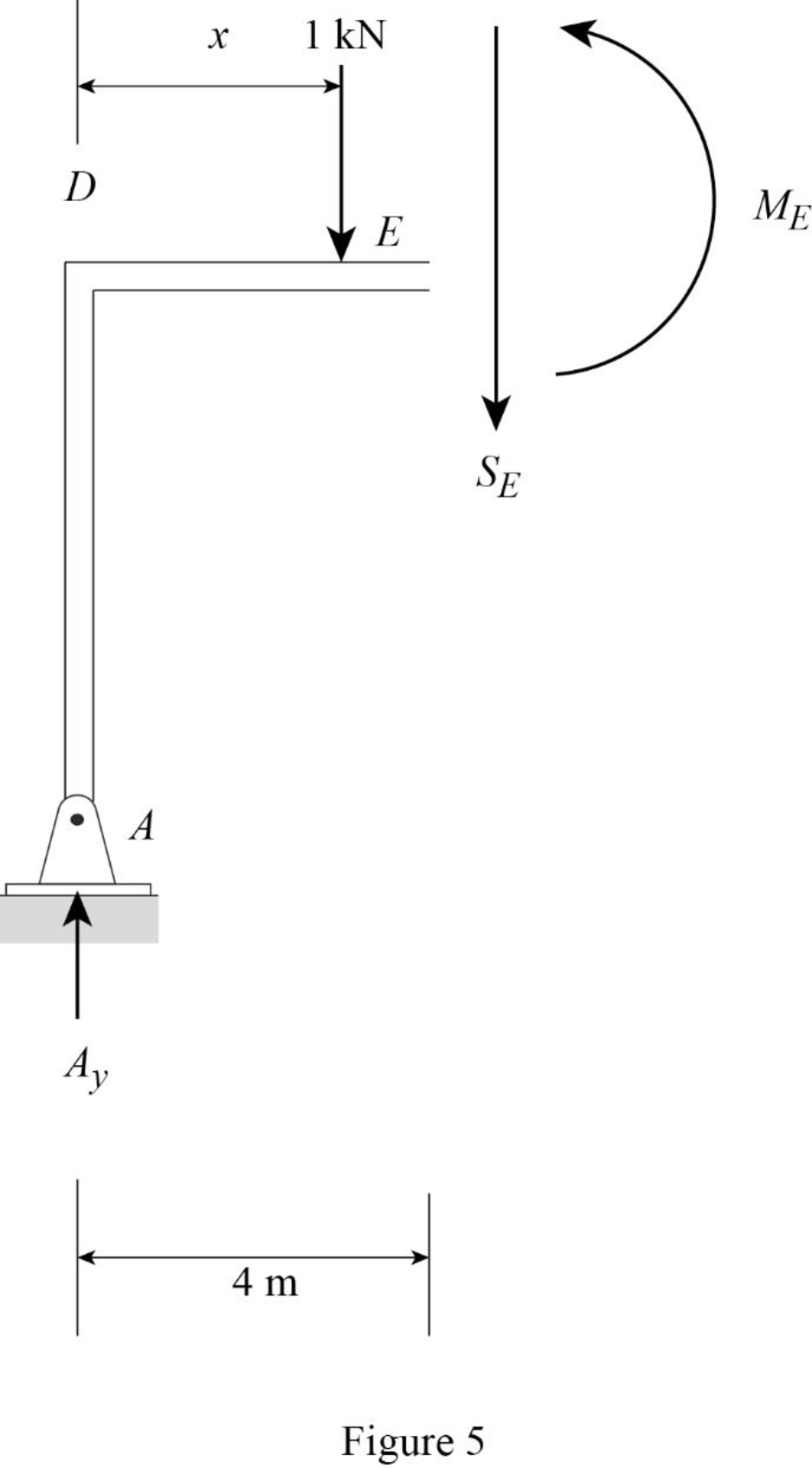
Refer Figure 5.
Apply equilibrium equation of forces.
Consider upward force as positive
Find the equation of shear force at E of portion DE
Substitute
Find the equation of shear
Apply 1 kN just right of E.
Consider section DE.
Sketch the free body diagram of the section DE as shown in Figure 6.
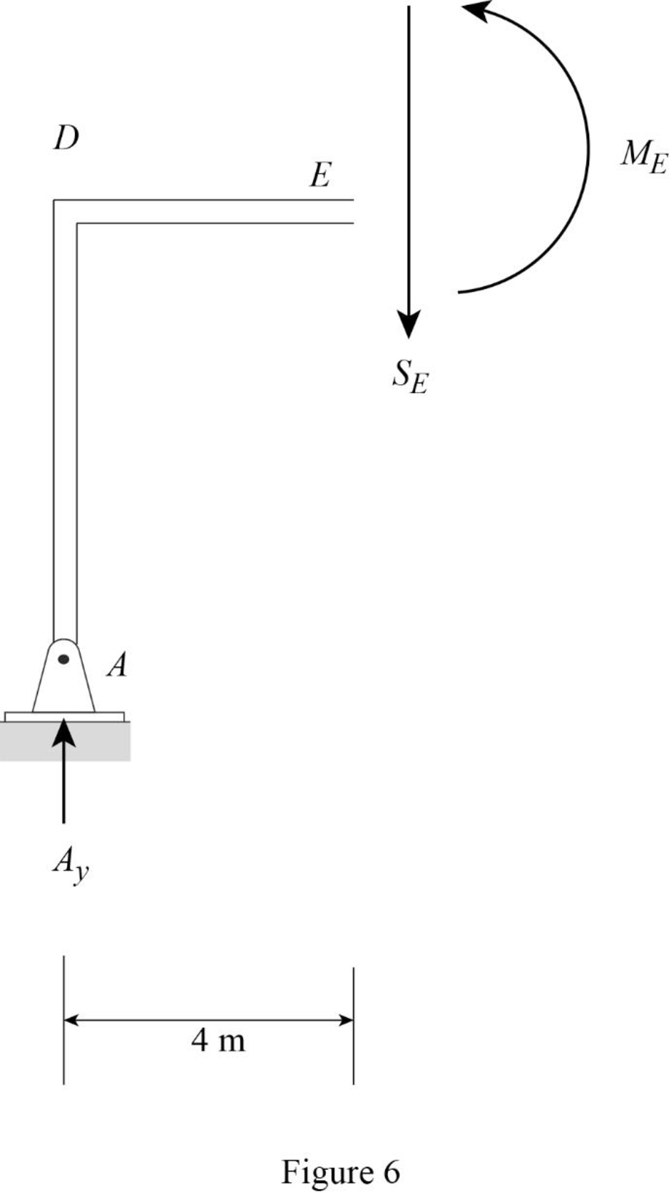
Refer Figure 6.
Apply equilibrium equation of forces.
Consider upward force as positive
Find the equation of shear force at E of portion EG
Substitute
Find the equation of shear force at E of portion GH
Substitute
Thus, the equations of the influence line for
Find the influence line ordinate of
Substitute 4 m for
Thus, the influence line ordinate of
Find the shear force of
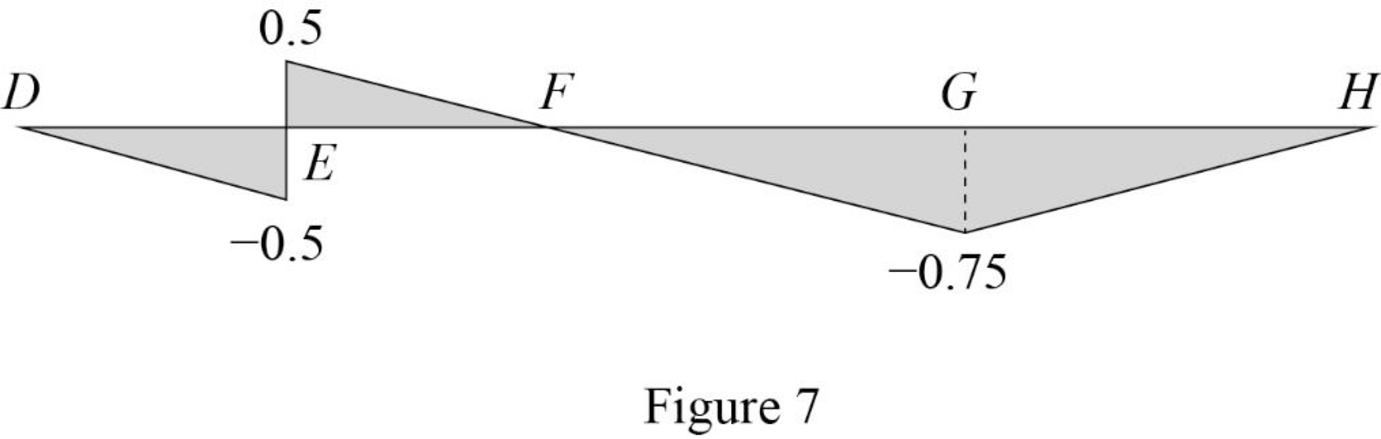
| x (m) | Points | Influence line ordinate of |
| 0 | D | 0 |
| 4 | ||
| 4 | ||
| 8 | F | 0 |
| 14 | G | |
| 20 | H | 0 |
Draw the influence lines for the shear force at point E using Table 4 as shown in Figure 7.
Influence line for moment at point E.
Refer Figure 5.
Consider section DE.
Consider clockwise moment as positive and anticlockwise moment as negative.
Take moment at E.
Find the equation of moment at E of portion DE
Substitute
Refer Figure 6.
Consider section DE.
Find the equation of moment at E of portion EH
Consider clockwise moment as positive and anticlockwise moment as negative.
Take moment at E.
Find the equation of moment at E of portion EF.
Find the equation of moment at E of portion EG
Substitute
Find the equation of moment at E of portion GH
Substitute
Thus, the equations of the influence line for
Find the influence line ordinate of
Substitute 4 m for
Thus, the influence line ordinate of
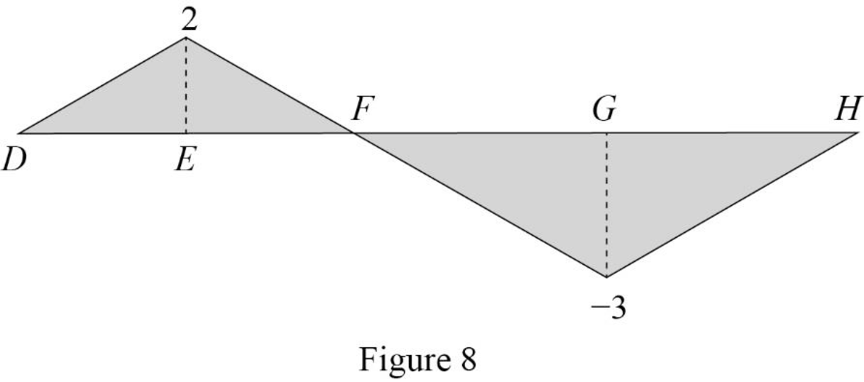
Find the moment at various points of x using the Equations (15), (16), and (17) and summarize the value as in Table 5.
| x (m) | Points | Influence line ordinate of |
| 0 | D | 0 |
| 4 | E | 2 |
| 8 | F | 0 |
| 14 | G | |
| 20 | H | 0 |
Draw the influence lines for the moment at point E using Table 5 as shown in Figure 8.
Therefore, the influence lines for the vertical reactions at supports A, B, and C and the influence lines for the shear and bending moment at point E are drawn.
Want to see more full solutions like this?
Chapter 8 Solutions
Structural Analysis


- Problem 3 15 A W150 x 37 rolled-steel beam is used below. Let P150 kN, L-10 m and E 200 GPa. Find the deflection and slope at each node and each pin or wall reaction. If a software program such Maple or MATLAB issued as part of the solution, a hard copy of the code must be submitted too. 1/2 1/2arrow_forward1. Determine the bearings, azimuths, and lengths of lines AB, BC, CD, and DA for the closed loop traverse data shown below in Table 1. Show calculations. Table 1 Station Northing [ft] Easting [ft] A 1,000 1,000 B 750 1,750 C 1,345 2,255 D 1,567 1,345 2. Compute the bearings of sides BC and CD in Figure 1. Show all work for all angles. A B 70°10' S72°39'W C 94°35' Figure 1 Tt (+) B Darrow_forwardhoph - AT 10x AT 10.076 ht 0.076 0 0-1846112 14884 xh T 1.632m h-4- (1-22) h = 1.022m 14. The 4-ft-diameter cylinder, 4 ft long, is acted upon by water on the left and oil of sp gr 0.800 on the right. Determine (a) the normal force at B if the cylinder weighs 4000 lb and (b) the horizontal force due to oil and water if the oil level drops 1 ft. Solution Water Oil Barrow_forward
- 3. The following data was collected for the traverse shown in Figure 2. a. Determine the latitudes and departures for all sides. b. Determine the linear error of closure and the accuracy ratio. C. Correct and balance the latitudes and departures. A N80°27'E 467.81 ft 497.50 ft N56°46' W B S34°51'E 483.69 ft 325.06 ft D N81°48' Warrow_forwardPlease answer the questions in the picture. Thank you for your help!arrow_forward1500 N A B 3500 N/m 1.2 m 3.6 m 1.2 m 1800 N Beam Cross-section: 4b T D b 25 mm 100 mm For beam ABCD with cross-section shown, design the beam by determining the following: Draw the shear and bending moment diagrams (show your detailed computations to get credit) The minimum dimension for b [mm], knowing that the allowable flexural stress and transverse shear stress are 10 MPa and 0.5 MPa, respectively.arrow_forward
- Civil engineering quantiarrow_forwardPlease answer the questions in the picture. Thank you for your help. For part B use the Second Picture.arrow_forwardDerive by deconvolution the six-hour unit hydrograph from the following data for a watershed having a drainage area of 216 km2 , assuming a constant rainfall abstraction rate and a constant baseflow of 20 m3 /s. Six-hour period 1 2 3 4 5 6 7 8 9 10 11 Rainfall (cm) 1.5 3.5 2.5 1.5 Streamflow (m3 /s) 26 71 174 226 173 99 49 33 26 22 21 Use the unit hydrograph developed to calculate the streamflow hydrographfrom a 12 hour-duration storm having 2 cm of rainfall excess in the first six hours and 3 cm inthe second six hours. Assume a constant baseflow rate of 30 m3/s.arrow_forward
- Please answer the following question in the picture. Thank you for your help.arrow_forwardGiven the unit hydrographic in the table, calculate the streamdlow hydrographic from a 12 hour duration story having 2cm of rainfall excess in the first six hours and 3cm in the second six hours. Assume a constant base flow rate of 30 m3/sarrow_forwardBased on the following information, what is the owner’s equity? Current Assets: $162,000Current Liabilities: $91,000 Fixed Assets: $290,000 long-Term Debt: $140,000arrow_forward