
Concept explainers
Draw the influence lines for the vertical reactions at supports A and C.
Draw the influence lines for the shear and bending moment at point B.
Explanation of Solution
Calculation:
Apply a 1 k unit moving load at a distance of x from left end A.
Sketch the free body diagram of beam as shown in Figure 1.
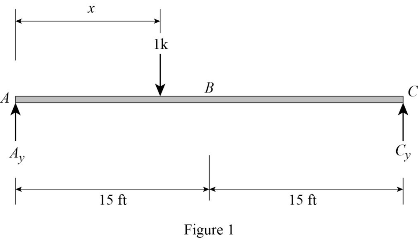
Refer Figure 1.
Find the equation of support reaction
Take moment about point C.
Consider moment equilibrium at point C.
Consider clockwise moment as positive and anticlockwise moment as negative
Sum of moment at point C is zero.
Find the equation of support reaction
Apply vertical equilibrium equation of forces.
Consider upward force as positive
Substitute
Consider Equation (1).
Find the value of influence line ordinate of reaction
Substitute 0 for x in Equation (1).
Similarly calculate the influence line ordinate of reaction
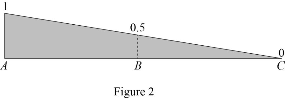
| x | |
| 0 | 1 |
| 15 | 0.5 |
| 30 | 0 |
Draw the influence line diagram for the vertical reactions at support A using Table 1 as shown in Figure 2.
Consider Equation (2).
Find the influence line ordinate of reaction
Substitute 30 for x in Equation (2).
Similarly calculate the influence line ordinate of reaction
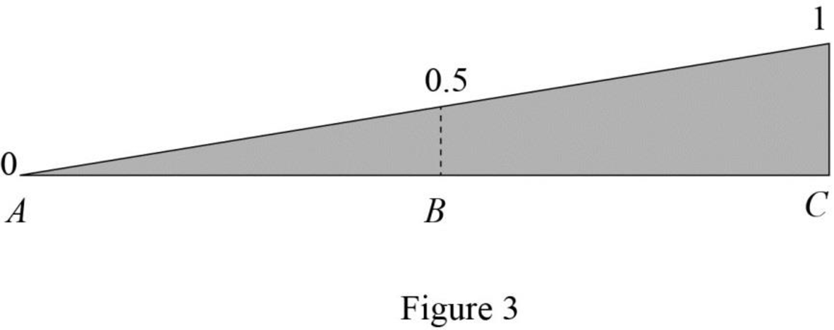
| x | |
| 0 | 0 |
| 15 | 0.5 |
| 30 | 1 |
Draw the influence line diagram for the vertical reactions at support C using Table 2 as shown in Figure 3.
Find the equation of shear force at B of portion AB
Sketch the free body diagram of the section AB as shown in Figure 4.
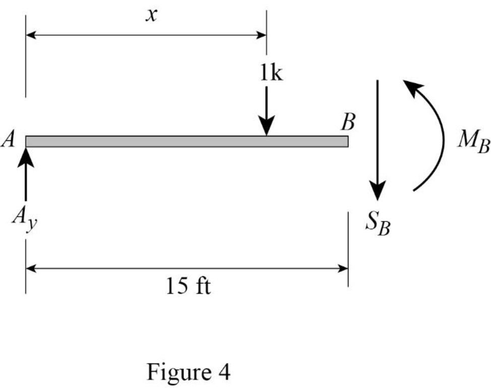
Refer Figure 4.
Apply equilibrium equation of forces.
Consider upward force as positive
Substitute
Find the equation of shear force at B of portion BC
Sketch the free body diagram of the section BC as shown in Figure 5.
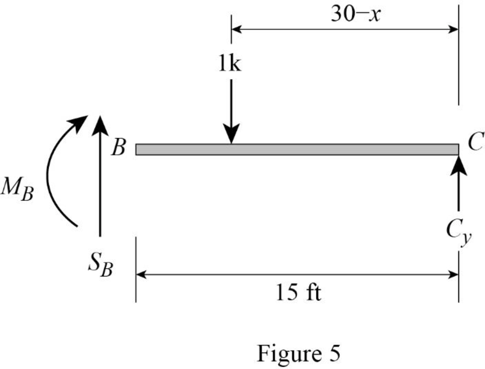
Refer Figure 5.
Apply equilibrium equation of forces.
Consider upward force as positive
Substitute
Thus, the equations of the influence line for
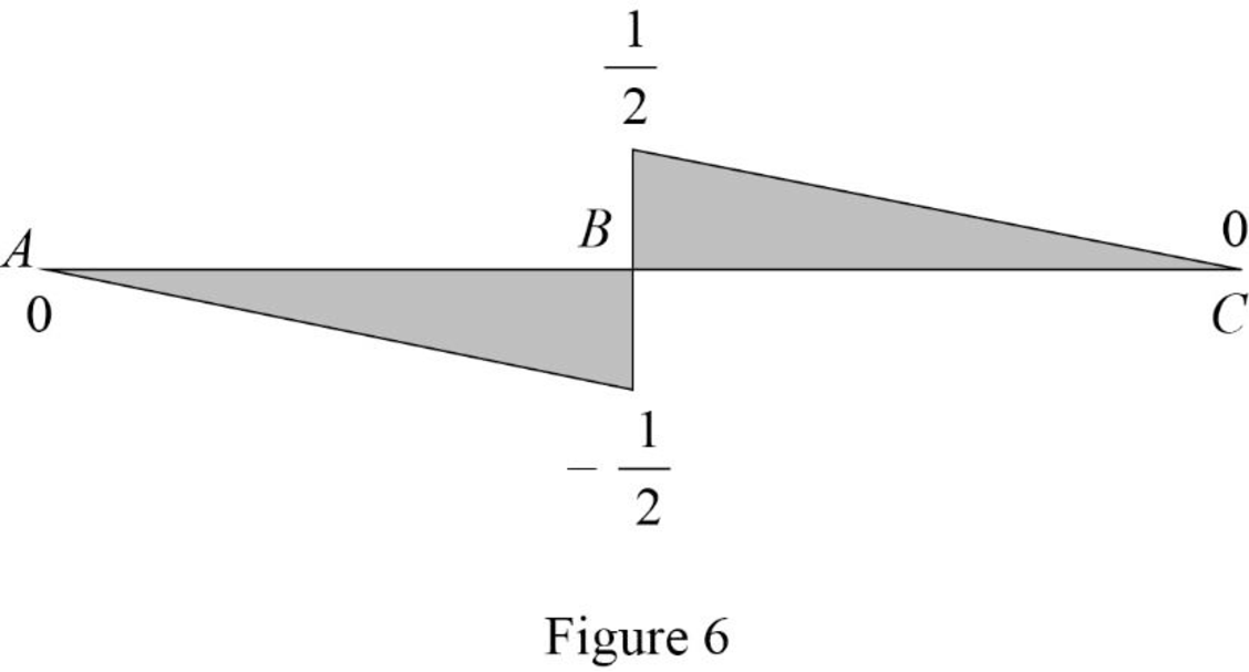
Find the value of influence line ordinate of shear force at various points of x using the Equations (3) and (4) and summarize the value as in Table 3.
| x | |
| 0 | 1 |
| 30 | 0 |
Draw the influence lines for the shear force at point B using Table 3 as shown in Figure 6.
Refer Figure 4.
Consider clockwise moment as positive and anticlockwise moment as negative.
Find the equation of moment at B of portion AB
Substitute
Refer Figure 5.
Consider clockwise moment as negative and anticlockwise moment as positive.
Find the equation of moment at B of portion BC
Substitute
Thus, the equations of the influence line for
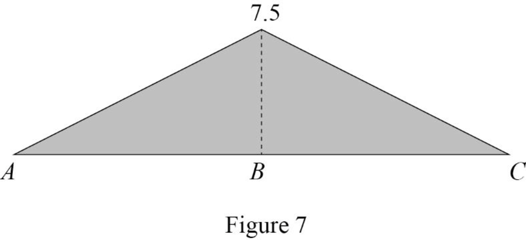
Find the value of influence line ordinate of moment at various points of x using the Equations (5) and (6) and summarize the value as in Table 4.
| x | |
| 0 | 0 |
| 30 | 0 |
Draw the influence lines for the moment at point B using Table 4 as shown in Figure 7.
Therefore, the influence lines for the vertical reactions at supports A and C and the influence lines for the shear and bending moment at point B are drawn.
Want to see more full solutions like this?
Chapter 8 Solutions
Structural Analysis


- 1) Assuming that water at 20 C is flowing through the system at a constant flow rate of 2 ft³/sec and neglecting viscous effects, calculate the EL and HGL at points A, B, and C. Sketch the EL and HGL alongside the diagram. A ZA = 55 ft D₁ = 3 in B D₂ = 6 in C 2) What is the elevation at point C in the above figure? 3) Using the figure from problem 1, sketch the EL and HGL accounting for both major and minor losses. Note that the flow rate will change due to the introduction of friction (we will explore this further in the coming weeks). You do not need to calculate the values of EL and HGL.arrow_forward8) Carbon dioxide at 20 C is transported through a pipe of 0.1 m in diameter. What is the maximum flow rate possible to achieve laminar flow?arrow_forward7) In the below diagram, the pipe diameter is 10 cm and the flow rate in the pipe is 0.3 m³/sec. At this flow rate, the pump will generate 90 m of head. The pressure at point A is 500 Pa and the water in the pipe is at 60 C. a) Taking the datum to be at the centerline of the pump, calculate the EL and HGL at points A and B, neglecting friction. b) What is the pressure at point B? A P Barrow_forward
- C 7-33. The beam is constructed from two boards fastened together at the top and bottom with three rows of nails spaced every 8 in. If an internal shear force of V = 800 lb is applied to the boards, determine the shear force resisted by each nail. Temps to rise Sunday **SW4 88AN SID IDI FI 2 F2 # * F3 3 日 $ 4 Q W A S F4 B Q Search F7 40 F5 F6 & Jo % 5 6 7 E R T Y ப * F G H J FB IA F9 IAA FIO FII ( B 9 ㅁ Z X C V B N M ALT H FI2 8 in. =1 } ㅁ P [ ] L 8 in. 2 in. 4 in. V 9 in. DELETE BACKSPACE NUM LOCK I T ENTER PAUSE SHIFT ALT CTRL V 7 HOME الحاد E I ENDarrow_forwardG 6-114. The cantilever wide-flange steel beam is subjected to the concentrated force of P = 600 N at its end. Determine the maximum bending stress developed in the beam at section A. 10 mm 150 mm 10 mm y Temps to rise Sunday @ 2 *F3 *F2 $ # 4 3 Q Search 1+ F7 48 F5 FB F4 & % 5 6 7 4 W E R T Y ப IAA FB * 8 9 ► I 30° FIO Q FII FI2 + == 200 mm HI [ ] A 5 ㅁ F G H J K L ? PAUSE Z X C V B N M ALT ALT CTRL -10 mm DELETE 2 m A BACKSPACE NUM LOCK 2:27 PM 4/10/2025 INSERT PE 7 日 9 HOME PG U ENTER 4 S SHIFT 2 END INSarrow_forward*7-16. allow The beam has a square cross section and is made of wood having an allowable shear stress of T - 1.4 ksi. If it is subjected to a shear of V = 1.5 kip, determine the smallest dimension a of its sides. 2 Temps to rise Sunday Fl BID (0) 4 3 2 Q Search F4 40 FS * & % S 6 7 D W E R T Y ப A S ㅁ F G H J Z X C V B N ALT の 日 Σ H FID FII FIE L ALT CTAL [ ] PAUSE V-1.5 kip BELETE BACKSPACE NUM LOCA 7 HOME ENTER F SHIFT ENDarrow_forward
- 1. Determine the reaction at supports and forces acting on each member. (5 pts each) 35 kN 60 kN 10 kN 1m 2m -3m -3m 3m 3m 25 kN 50 kN 10 kNarrow_forwardProblem 7 Water is flowing in a channel with a rectangular cross-section. The channel has a uniform width of b 10 m, and it is equipped with a broad-crested weir. The height of flow in a channel far upstream of the weir is h₁ 2 m, while the weir is == hweir = 0.8 m above the bed of the channel. = 1. Assuming the flow over the weir is critical, calculate the flow rate in the channel by iteratively solving for the critical depth he. Perform at least 3 iterations. Did the flow rate converge? 2. Given the water depth immediately downstream of the weir is 90% of the critical depth hc, what is the water depth after the flow experiences a hydraulic jump further downstream? 3. How much energy is dissipated by the hydraulic jump? h₁ hweir Figure 7: A subcritical flow goes over a broad-crested weir, and it experiences a hydraulic jump downstream of the weir. Figure not to scale.arrow_forwardmasonry worksarrow_forward
- A cantilever beam ABC is fixed at legment AB is 2m long and BC is 3m long. Segmen BC is loaded with a triangular load ranging from 0 at Calculate the maximum slope of the beam. Compute the maximum deflection.arrow_forwardSTRUCTURAL ANALYSISarrow_forwardA 6m simply supported beam is loaded with a 12 kN-m concentrated moment placed 2m from the left support and a concentrated load of 24 kN located 2m from the right support. The flexural rigidity of the beam is EI. Calculate the slope of the tangent at the left support. Determine the rotation at the right support. Find the deflection at the point of application of concentrated moment. What is the maximum deflection of the beam?arrow_forward