
Concept explainers
Draw the influence lines for the reaction moment at support A, the vertical reactions at supports A and F and the shear and bending moment at point E.
Explanation of Solution
Calculation:
Influence line for moment at support A.
Apply a 1 kN unit moving load at a distance of x from left end C.
Sketch the free body diagram of frame as shown in Figure 1.
Refer Figure 1.
Apply 1 kN load just left of C
Take moment at A from B.
Consider clockwise moment as positive and anticlockwise moment as negative.
Apply 1 kN load just right of C and just left of D
Take moment at A from D.
Apply 1 kN load just right of D and just right of F
Take moment at A from F.
Thus, the equation of moment at A as follows,
Find the influence line ordinate of
Substitute 0 for
Find the influence line ordinate of
The vertical reaction at F is 1 kN when 1 kN applied at F.
Substitute 20 m for
Thus, the influence line ordinate of
Similarly calculate the influence line ordinate of
| x (m) | Points | Influence line ordinate of |
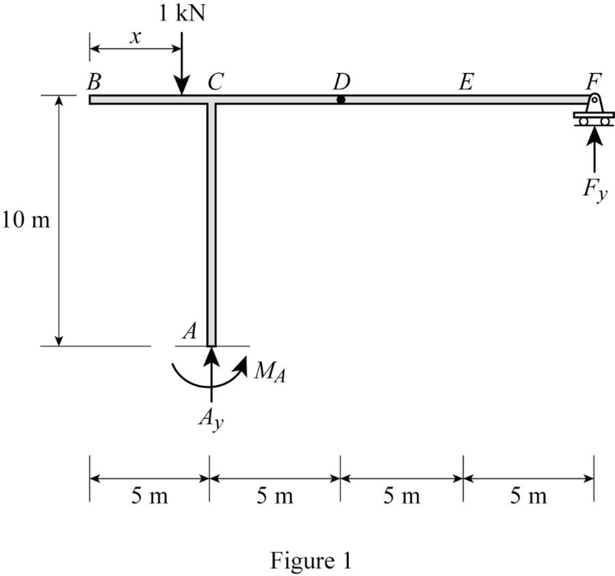
| 0 | B | ‑5 |
| 5 | C | 0 |
| 10 | D | 5 |
| 20 | F | 0 |
Sketch the influence line diagram for the moment at support A using Table 1 as shown in Figure 2.
Influence line for vertical reaction at support F.
Apply a 1 kN unit moving load at a distance of x from left end C.
Refer Figure 1.
Find the vertical support reaction
Apply 1 kN load just left of D
Consider section DF.
Consider moment equilibrium at point D.
Consider clockwise moment as positive and anticlockwise moment as negative
Apply 1 kN load just right of D
Consider section DF.
Consider moment equilibrium at point D.
Consider clockwise moment as positive and anticlockwise moment as negative
Thus, the equation of vertical support reaction at F as follows,
Find the influence line ordinate of
Substitute 20 for
Thus, the influence line ordinate of
Similarly calculate the influence line ordinate of
| x (m) | Points | Influence line ordinate of |
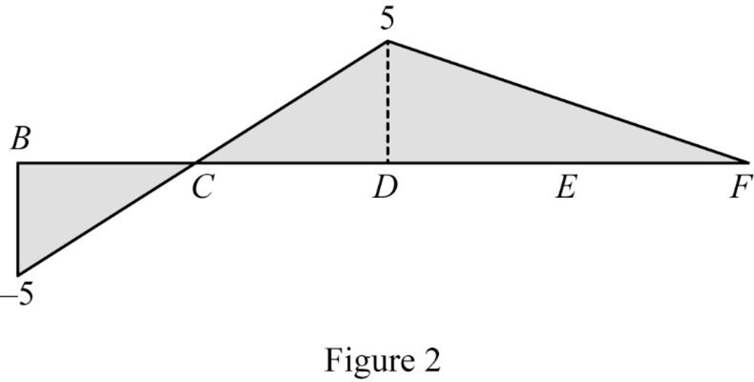
| 0 | B | 0 |
| 5 | C | 0 |
| 10 | D | 0 |
| 15 | E | 0.5 |
| 20 | F | 1 |
Sketch the influence line diagram for the vertical reaction at support F using Table 2 as shown in Figure 3.
Influence line for vertical reaction at support A.
Apply a 1 kN unit moving load at a distance of x from left end C.
Refer Figure 1.
Apply vertical equilibrium in the system.
Consider upward force as positive and downward force as negative.
Find the equation of vertical support reaction
Substitute 0 for
Find the equation of vertical support reaction
Substitute
Thus, the equation of vertical support reaction at A as follows,
Find the influence line ordinate of
Substitute 20 m for
Thus, the influence line ordinate of
Similarly calculate the influence line ordinate of
| x (m) | Points | Influence line ordinate of |
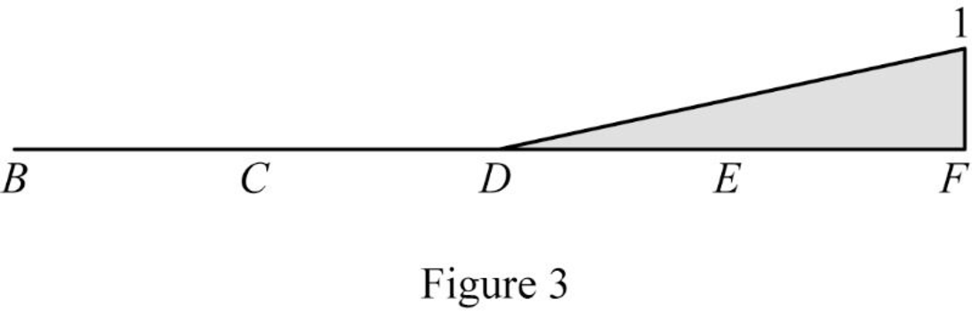
| 0 | B | 1 |
| 5 | C | 1 |
| 10 | D | 1 |
| 15 | E | 0.5 |
| 20 | F | 0 |
Sketch the influence line diagram for the vertical reaction at support A using Table 3 as shown in Figure 4.
Influence line for shear at point E.
Sketch the free body diagram of the section BD as shown in Figure 5.
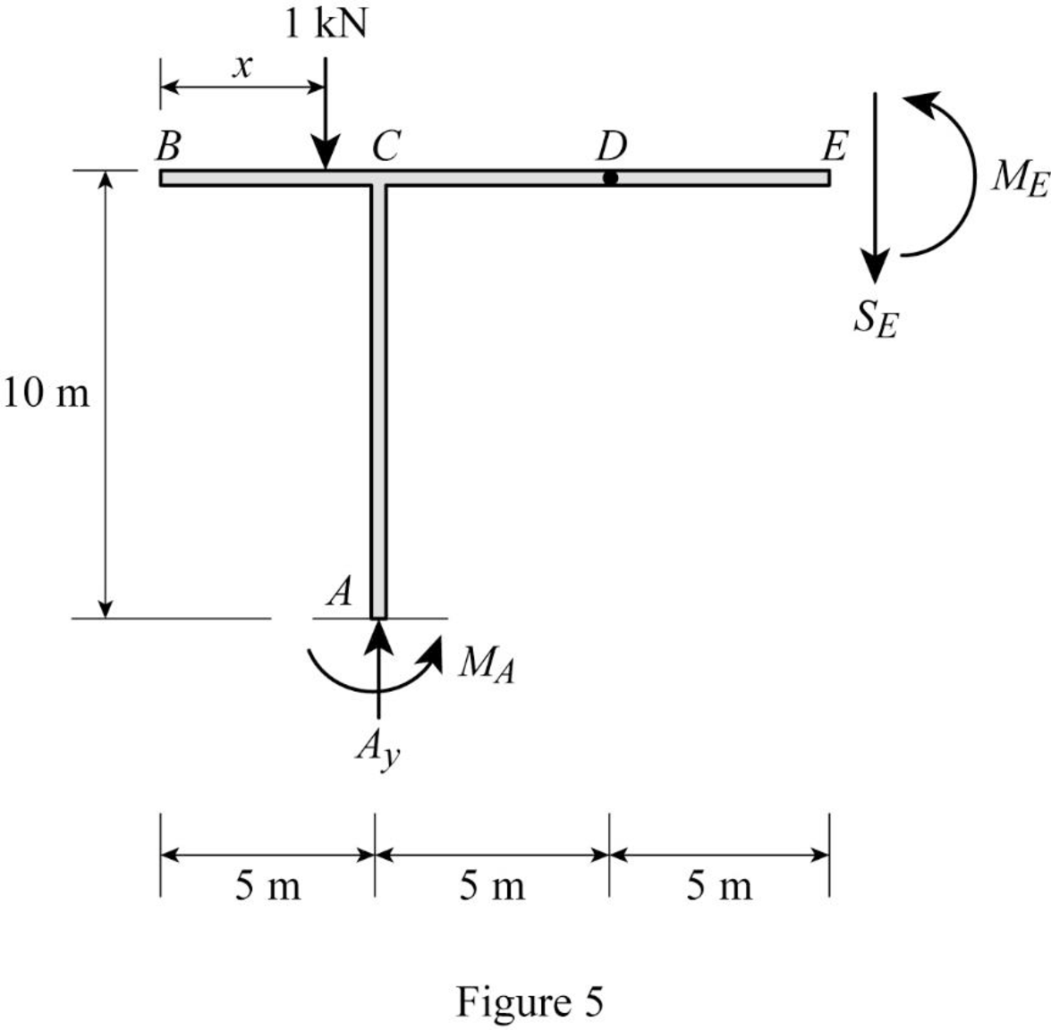
Refer Figure 5.
Apply equilibrium equation of forces.
Consider upward force as positive
Find the equation of shear force at E of portion BD
Substitute
Find the equation of shear force at E of portion DE
Substitute
Find the equation of shear force at E of portion EF
Sketch the free body diagram of the section EF as shown in Figure 6.
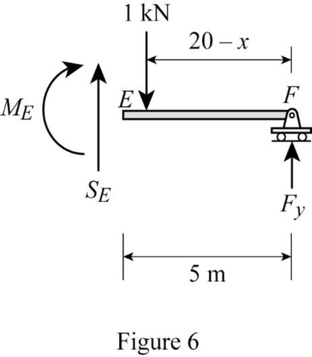
Refer Figure 6.
Apply equilibrium equation of forces.
Consider upward force as positive
Substitute
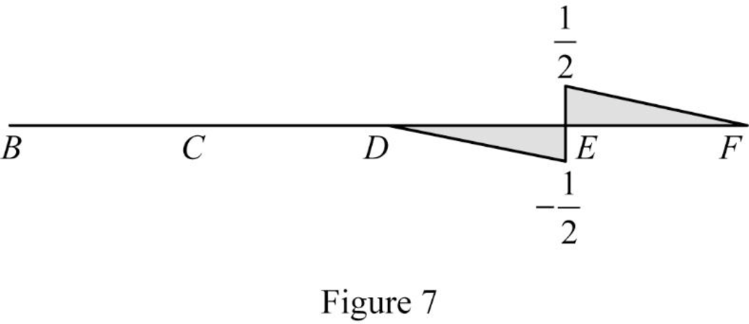
Thus, the equations of the influence line for
Find the influence line ordinate of
Substitute 15 m for
Thus, the influence line ordinate of
Find the shear force of
| x (m) | Points | Influence line ordinate of |
| 0 | B | 0 |
| 5 | 0 | |
| 10 | 0 | |
| 15 | ||
| 15 | ||
| 20 | F | 0 |
Draw the influence lines for the shear force at point E using Table 4 as shown in Figure 7.
Influence line for moment at point E.
Refer Figure 5.
Consider section BE.
Consider clockwise moment as positive and anticlockwise moment as negative.
Take moment at E.
Find the equation of moment at E of portion BE.
Find the equation of moment at E of portion BD
Substitute
Find the equation of moment at E of portion DE
Substitute
Substitute
Refer Figure 6.
Consider section EF.
Find the equation of moment at E of portion EF
Consider clockwise moment as positive and anticlockwise moment as negative.
Take moment at E.
Find the equation of moment at E of portion EF.
Substitute
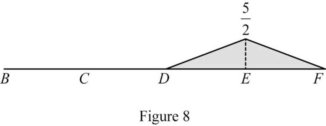
Thus, the equations of the influence line for
Find the influence line ordinate of
Substitute 15 m for
Thus, the influence line ordinate of
Find the moment at various points of x using the Equations (5) and (6) and summarize the value as in Table 5.
| x (m) | Points | Influence line ordinate of |
| 0 | B | 0 |
| 5 | C | 0 |
| 10 | D | 0 |
| 15 | E | |
| 20 | F | 0 |
Draw the influence lines for the moment at point E using Table 5 as shown in Figure 8.
Therefore, the influence lines for the vertical reactions at supports A and F and the influence lines for the shear and bending moment at point E are drawn.
Want to see more full solutions like this?
Chapter 8 Solutions
Structural Analysis, SI Edition


- nent 6-Transverse Shear & Deflection ↓ 2 of 2 -+ Automatic Zoom 4.) The built-up wooden beam shown is subjected to a vertical shear of 8 kN. Knowing the the nails are spaced longitudinally every 60 mm at A and every 25 mm at B, determine the shear force in the nails at A and B. (5 points) 50 300- 400 A 50 A C 150 B A 100 50 200 A B Dimensions in mm 5.) A 2.5 inch x 5.5 inch rectangular Southern pine section (E=1.8 x 10³ ksi) is used in an 8 ft cantilever span subjected to the loads shown. Compute the deflections at point A. (4 points) Дarrow_forwardE:/school%20pack/BENG%202/EG231/STATICS/LECTURE%20NOTES/PRACTICE%20QUESTIONS/EG%20231%20Chap-5%20Practice%20Que PDF 豆豆豆豆豆豆 aw V Aa | Ask Copilot - + 4 of 8 D 3. Calculate the y-coordinate of the centroid of the shaded area. 74 mm y 3232 mm mm DELL 32 mm -x F1 F2 F3 F4 F5 F6 F7 F8 F9 prt sc F10 home end F11 F 2 W E3 $ 4 € 95 % & 6 7 8 * 00 R T Y כ 9 O Parrow_forward*8-60. The 2-in.-diameter rod is subjected to the forces shown. Determine the state of stress at point B, and show the results on a differential element located at this point. Probs. 8-59/60 B 8 in. 600 lb 12 in. 500 lb 800 lbarrow_forward
- find SFD and BMD by using slope deflection methodarrow_forwardThe following relates to Problems 4 and 5. Christchurch, New Zealand experienced a major earthquake on February 22, 2011. It destroyed 100,000 homes. Data were collected on a sample of 300 damaged homes. These data are saved in the file called CIEG315 Homework 4 data.xlsx, which is available on Canvas under Files. A subset of the data is shown in the accompanying table. Two of the variables are qualitative in nature: Wall construction and roof construction. Two of the variables are quantitative: (1) Peak ground acceleration (PGA), a measure of the intensity of ground shaking that the home experienced in the earthquake (in units of acceleration of gravity, g); (2) Damage, which indicates the amount of damage experienced in the earthquake in New Zealand dollars; and (3) Building value, the pre-earthquake value of the home in New Zealand dollars. PGA (g) Damage (NZ$) Building Value (NZ$) Wall Construction Roof Construction Property ID 1 0.645 2 0.101 141,416 2,826 253,000 B 305,000 B T 3…arrow_forwardfind SFD and BMDarrow_forward
- The data needed to answer this question is given by this link: https://docs.google.com/spreadsheets/d/1vzb03U7Uvzm7X-by3OchQNwYeREzbP6Z-xzZMP2tzNw/edit?usp=sharing if it is easier to make a copy of the data because it is on view only then feel free to do so.arrow_forwardThe data needed to answer this question is given in the following link (file is on view only so if you would like to make a copy to make it easier for yourself feel free to do so) https://docs.google.com/spreadsheets/d/1aV5rsxdNjHnkeTkm5VqHzBXZgW-Ptbs3vqwk0SYiQPo/edit?usp=sharingarrow_forwardA k 000 6 ft A kips Bl D ft C C kips 10 ft 12 ft E B k/ft D E ft tarrow_forward
