
Concept explainers
Draw the influence lines for the shear and bending moment at point B.
Draw the influence lines for the shear at internal hinge C.
Explanation of Solution
Calculation:
Influence line for shear at point B:
Apply a 1 kN unit moving load at a distance of x from left end A.
Sketch the free body diagram of frame as shown in Figure 1.
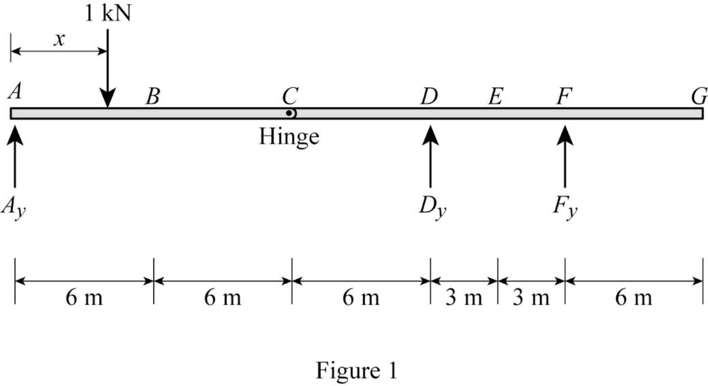
Refer Figure 1.
Consider the unit load at a variable position x to the left hinge C. (placed portion AC of the beam
Find the vertical support reaction
Take Moment at hinge C from left end A.
Consider clockwise moment as positive and anticlockwise moment as negative.
Consider the unit load at a variable position x to the right hinge C. (Place portion CG of the beam
Find the vertical support reaction
Take Moment at hinge C from left end A.
Consider clockwise moment as positive and anticlockwise moment as negative.
Thus, the equations of the influence line ordinate for
Refer Figure 1.
Find the equation of influence line ordinate for the vertical reaction
Apply moment equilibrium at F.
Consider clockwise moment as positive and anticlockwise moment as negative.
Find the influence line ordinate of vertical reaction
Substitute
Find the influence line ordinate of vertical reaction
Substitute
Thus, the equations of the influence line ordinate for
Refer Figure 1.
Find the equation of influence line ordinate for the vertical reaction
Consider the vertical forces equilibrium condition, take the upward force as positive
Find the influence line ordinate of vertical reaction
Substitute
Find the influence line ordinate of vertical reaction
Substitute
Thus, the equations of the influence line ordinate for
Find the equation of shear at B of portion AB
Sketch the free body diagram of the section AB as shown in Figure 2.
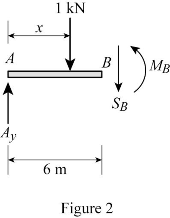
Refer Figure 2.
Apply equilibrium equation of forces.
Consider upward force as positive
Substitute
Find the equation of shear at B of portion BG
Sketch the free body diagram of the section BG as shown in Figure 3.
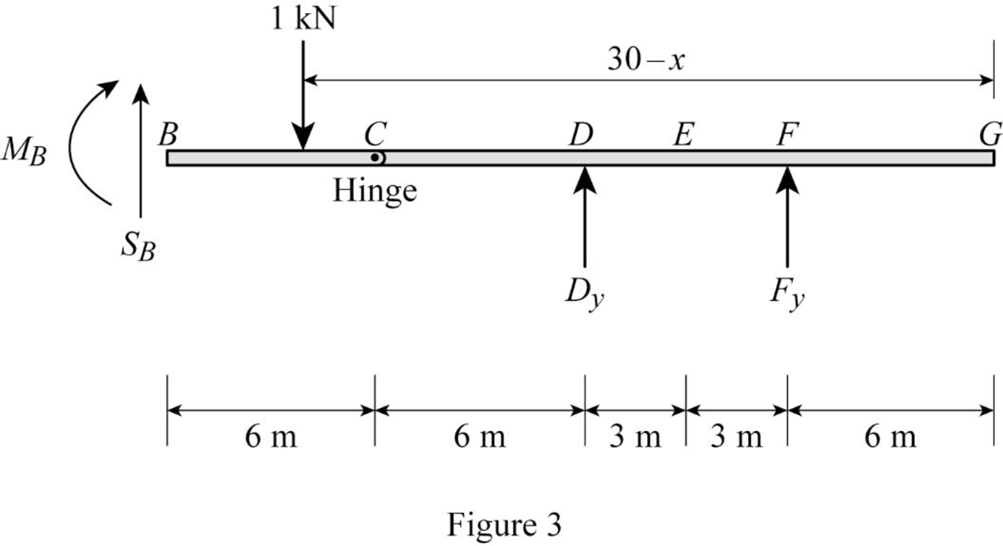
Refer Figure 3.
Apply equilibrium equation of forces.
Consider upward force as positive
Find the influence line ordinate of shear at B
Substitute
Find the influence line ordinate of shear at B
Substitute
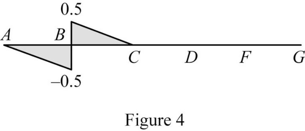
Thus, the equations of the influence line ordinate for
Find the influence line ordinate of
| x (m) | Points | Influence line ordinate of |
| 0 | A | 0 |
| 6 | ‑0.5 | |
| 6 | 0.5 | |
| 12 | C | 0 |
| 18 | D | 0 |
| 21 | E | 0 |
| 24 | F | 0 |
| 30 | G | 0 |
Sketch the influence line diagram for the shear at pointB as shown in Figure 4.
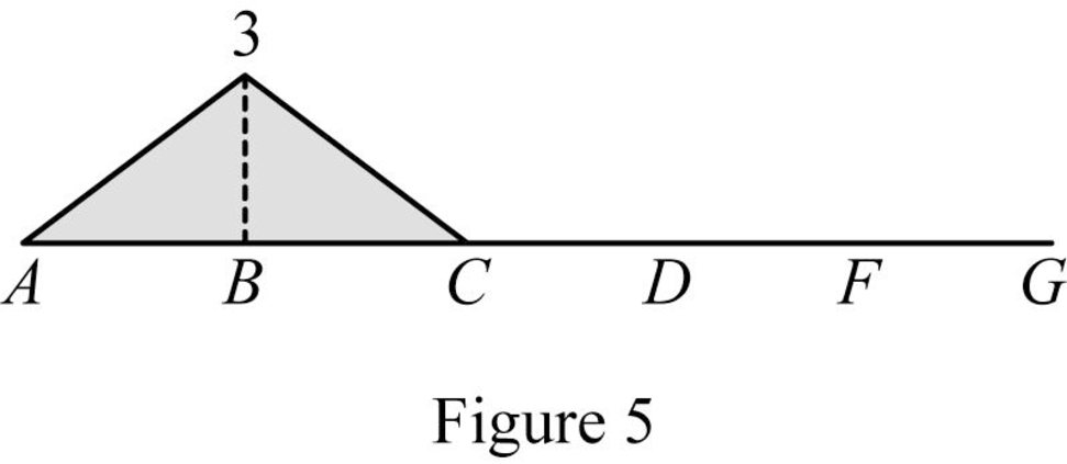
Influence line for moment at point B:
Refer Figure 2.
Find the equation of bending moment at B of portion AB
Take moment at B.
Consider clockwise moment as positive and anticlockwise moment as negative.
Substitute
Refer Figure 3.
Find the equation of bending moment at B of portion BG
Take moment at B.
Consider clockwise moment as negative and anticlockwise moment as positive.
Find the influence line ordinate of moment at B
Substitute
Find the influence line ordinate of moment at B
Substitute
Thus, the equations of the influence line ordinate for
Find the influence line ordinate of
| x (m) | Points | Influence line ordinate of |
| 0 | A | 0 |
| 6 | ‑3 | |
| 12 | C | 0 |
| 18 | D | 0 |
| 21 | E | 0 |
| 24 | F | 0 |
| 30 | G | 0 |
Sketch the influence line diagram for the bending moment at point B as shown in Figure 5.
Influence line for shear at hinge C:
Apply a 1 kN unit moving load at a distance of x from left end A.
Sketch the free body diagram of frame as shown in Figure 6.
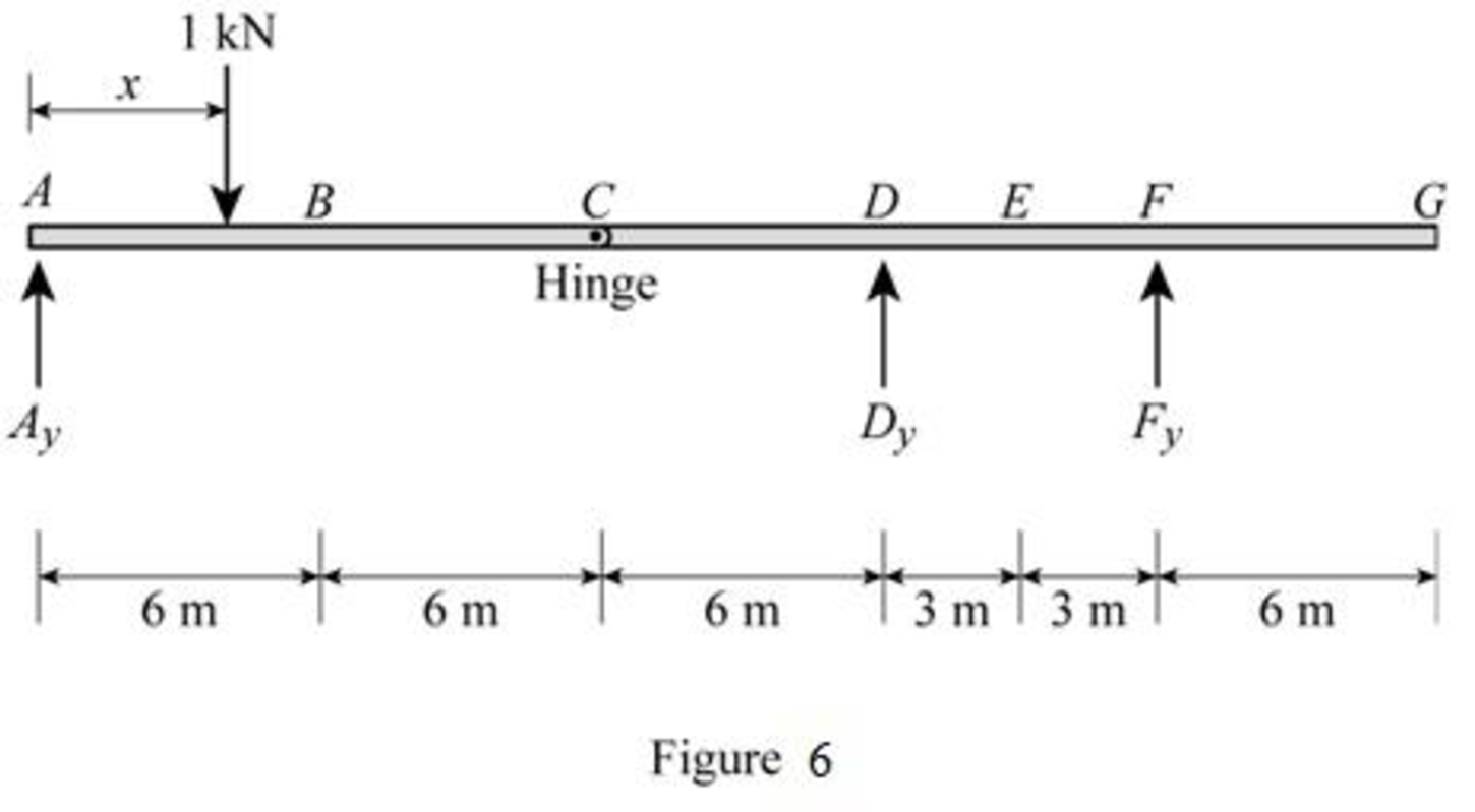
Refer Figure 6.
Consider the unit load at a variable position x to the left hinge C. (placed portion AC of the beam
Find the vertical support reaction
Take Moment at hinge C from left end A.
Consider clockwise moment as positive and anticlockwise moment as negative.
Consider the unit load at a variable position x to the right hinge C. (Place portion CG of the beam
Find the vertical support reaction
Take Moment at hinge C from left end A.
Consider clockwise moment as positive and anticlockwise moment as negative.
Thus, the equations of the influence line ordinate for
Refer Figure 1.
Find the equation of influence line ordinate for the vertical reaction
Apply moment equilibrium at F.
Consider clockwise moment as positive and anticlockwise moment as negative.
Find the influence line ordinate of vertical reaction
Substitute
Find the influence line ordinate of vertical reaction
Substitute
Thus, the equations of the influence line ordinate for
Refer Figure 1.
Find the equation of influence line ordinate for the vertical reaction
Consider the vertical forces equilibrium condition, take the upward force as positive
Find the influence line ordinate of vertical reaction
Substitute
Find the influence line ordinate of vertical reaction
Substitute
Thus, the equations of the influence line ordinate for
Find the equation of shear at C of portion AC
Sketch the free body diagram of the section AC as shown in Figure 7.
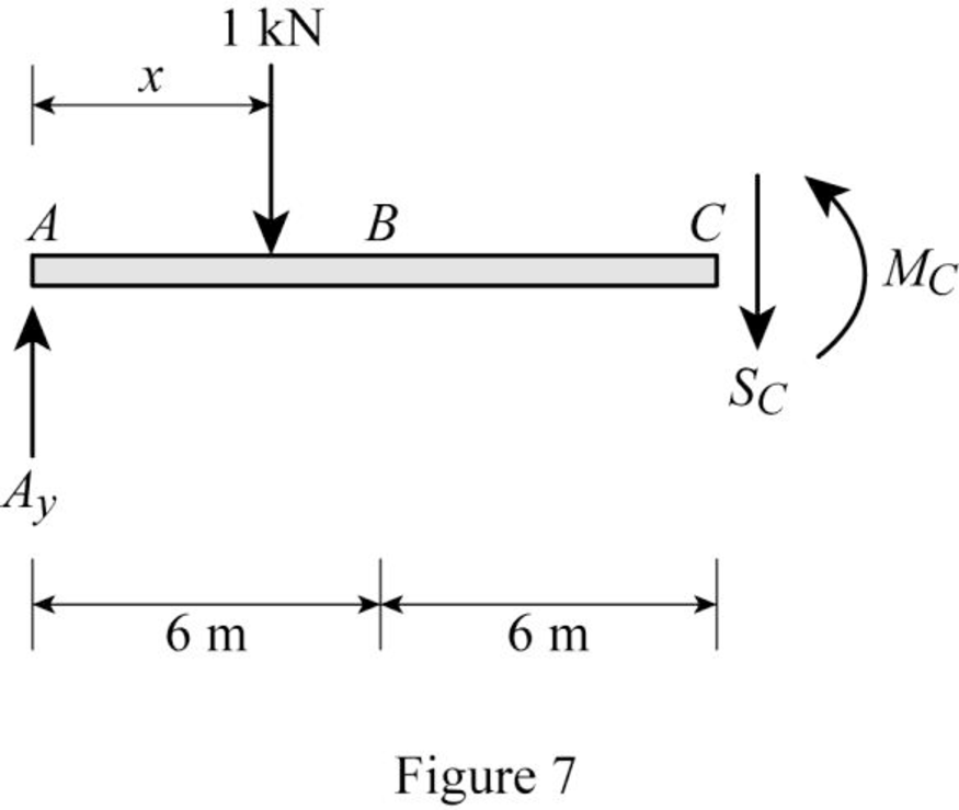
Refer Figure 7.
Apply equilibrium equation of forces.
Consider upward force as positive
Substitute
Find the equation of shear at C of portion CG
Sketch the free body diagram of the section CG as shown in Figure 8.
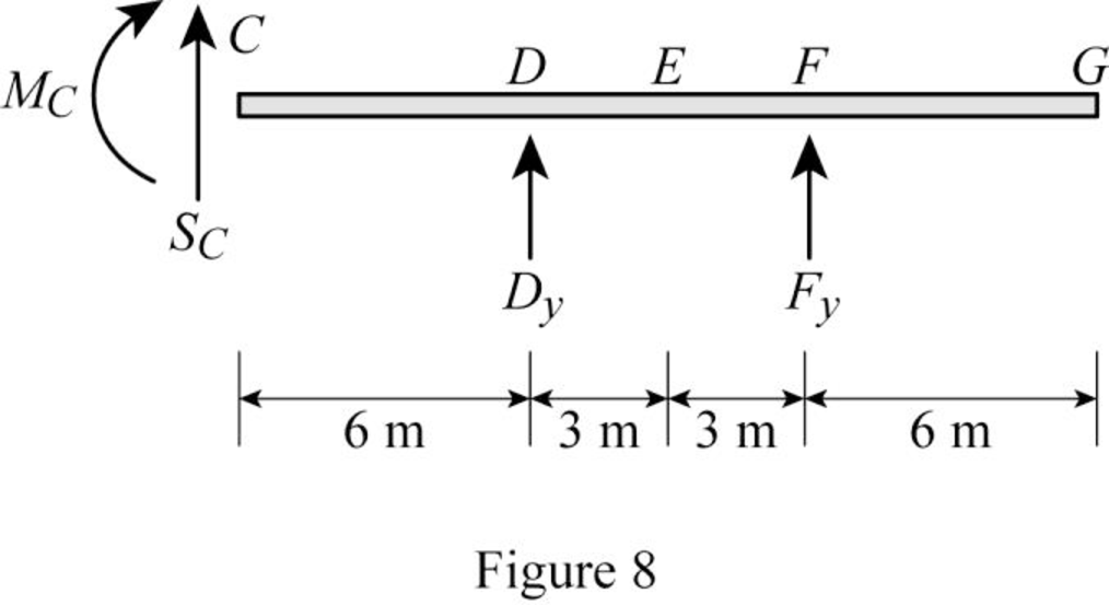
Refer Figure 8.
Apply equilibrium equation of forces.
Consider upward force as positive
Substitute
Thus, the equations of the influence line ordinate for
Find the influence line ordinate of
| x (m) | Points | Influence line ordinate of |
| 0 | A | 0 |
| 6 | ‑0.5 | |
| 12 | ‑1 | |
| 12 | 0 | |
| 18 | D | 0 |
| 21 | E | 0 |
| 24 | F | 0 |
| 30 | G | 0 |
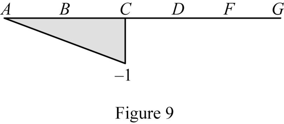
Sketch the influence line diagram for the shear at point C as shown in Figure 9.
Want to see more full solutions like this?
Chapter 8 Solutions
Structural Analysis, SI Edition


- Given an existing two-story steel structure with interior columns spaced as shown in Fig.2. The columns are spaced at 18 ft in the North-South direction and at 30 ft in the East-West direction. An interior lower-story column is to be removed by adding newsteel girder as shown in Fig. 4. The floor dead loads and the roof dead loads are 70 psfand 18 psf respectively. The floor live loads and the roof live loads are 50 psf and20 psf respectively. All existing steel materials are ASTM A36 steel (Fy=36 ksi). Newgirder is ASTM A992 steel (Fy= 50 ksi). All columns are W8x31. Use the LRFD Method.Assumptions:1- The loads given include column and beam self weights.2- Existing beam and new girder are simply supported at both ends.3- New girder top flange is laterally braced at mid span and at girder ends only.4- Columns are continuous from foundation to roof and are prevented from sway atfloor level and at roof level in both directions.5- Columns are pin supported at foundation, at floor level,…arrow_forwardFindarrow_forwardDetermine the vertical reaction at A for the beam shown and a settlement of ½" at support B. a. 45.6 k b. 41.6 k c. 42.7 k d. 40.7 karrow_forward
- What is the horizontal reaction at A for the frame shown 4? a. 2.42 k b. 15.00 k c. 27.58 k d. 25.00 karrow_forwardDetermine the bending moment at support A for the beam shown using the slope-deflection method. Use the sign convention defined in the chapter. a. 232.9 k-ft b. -182.1 k-ft c. 182.1 k-ft d. -232.9 k-ftarrow_forwardWhat is the shear and normal stresses of Point J and Point K?arrow_forward
- What are the states of stress (magnitude and tension/compression of the normal stresses and shear stress) at Point J and Point K?arrow_forwardConsider, M people (aka pax) who want to travel by car from O to D. They all start working at D at Q (e.g., Q-8am). If a person departs at time t, assume the time needed to go from O to D is given by c(t)=A+Bx(t), where x(t) is the flow of people departing at time t [car/unit of time]. In addition, a is the penalty for being early at work (E(t) is how early the person arrived when departing at time t), and ẞ is the penalty for being late at work (L(t) is how late the person arrived when departing at time t). Assume 0 < a < 1 < ß. Further assume the departure time choice problem under the equilibrium conditions. Prove that the arrival time of people who depart when most of the M people start their trips is equal to Q.arrow_forwarda. A b. A 3. Sketch normal depth, critical depth and the water surface profile. Assume at A and B the water is flowing at normal depth. Label and Identify all curves (i.e., M1, S2, etc.) Yn > Ye Уп Ye Уп> Ус yarrow_forward2. Design a trapezoidal ditch to carry Q = 1000 cfs. The ditch will be a lined channel, gravel bottom with sides shown below on a slope of S = 0.009. The side slopes of the 20-ft wide ditch will be 1 vertical to 3 horizontal. a) Determine the normal depth of flow (yn) using the Normal value for Manning's n. b) If freeboard requirements are 25% of the normal depth, how deep should the ditch be constructed? c) Classify the slope. T b Уп Z 1 Yn + FBarrow_forwardP15.45 WP A stainless steel pipe (Figure P15.45) with an outside diameter of 2.375 in. and a wall thickness of 0.109 in. is subjected to a bending moment M = 50 lb ft and an internal pressure of 180 psi. Determine the absolute maximum shear stress on the outer surface of the pipe. M FIGURE P15.45 Marrow_forward10.72 What power must the pump supply to the system to pump the oil from the lower reservoir to the upper reservoir at a rate of 0.3 m³/s? Sketch the HGL and the EGL for the system. p=940 kg/m³ v = 10-5 m²/s Elevation 100 m Elevation 112 m L= 150 m Oil Steel pipe D = 30 cm Problem 10.72arrow_forwardarrow_back_iosSEE MORE QUESTIONSarrow_forward_ios
