
Statics and Mechanics of Materials (5th Edition)
5th Edition
ISBN: 9780134382593
Author: Russell C. Hibbeler
Publisher: PEARSON
expand_more
expand_more
format_list_bulleted
Videos
Textbook Question
Chapter 7.8, Problem 81P
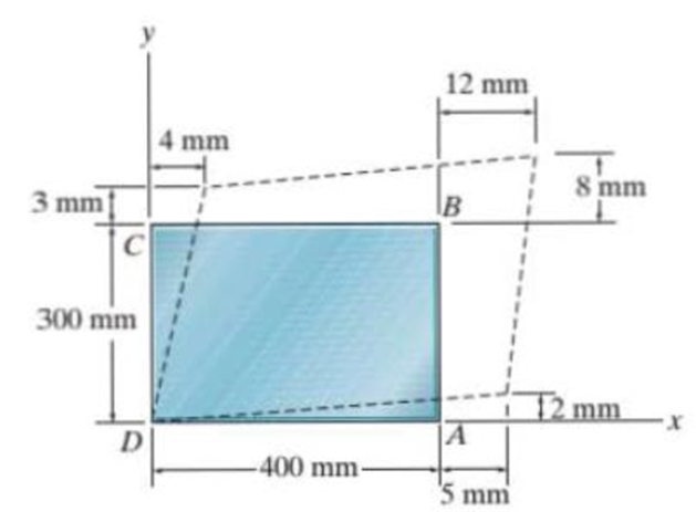
Determine the shear strain γxy at corners D and C if the plastic distorts as shown by the dashed lines.
Prob. 7–81
Expert Solution & Answer
Want to see the full answer?
Check out a sample textbook solution
Students have asked these similar questions
الثانية
Babakt
Momentum equation for Boundary Layer
S
SS
-Txfriction dray
Momentum equation for Boundary Layer
What laws are important for resolving
issues
2 How to draw.
3 What's Point about this.
R
αι
g
The system given on the left, consists of three pulleys and
the depicted vertical ropes.
Given:
ri
J₁, m1
R = 2r;
απ
r2, J2, m₂
m1; m2; M3
J1 J2 J3
J3, m3
a) Determine the radii 2 and 3.
B: Solid rotating shaft used in the boat with high speed shown in Figure. The amount of power transmitted at the
greatest torque is 224 kW with 130 r.p.m. Used DE-Goodman theory to determine the shaft diameter. Take the
shaft material is annealed AISI 1030, the endurance limit of 18.86 kpsi and a factor of safety 1. Which criterion
is more conservative?
Note: all dimensions in mm.
1
AA
Motor
300
Thrust
Bearing
Sprocket
100
9750
เอ
Chapter 7 Solutions
Statics and Mechanics of Materials (5th Edition)
Ch. 7.2 - In each case, explain how to find the resultant...Ch. 7.2 - Determine the internal normal force, shear force,...Ch. 7.2 - Determine the internal normal force, shear force,...Ch. 7.2 - Determine the internal normal force, shear force,...Ch. 7.2 - Determine the internal normal force, shear force,...Ch. 7.2 - Determine the internal normal force, shear force,...Ch. 7.2 - Determine the internal normal force, shear force,...Ch. 7.2 - The shaft is supported by a smooth thrust bearing...Ch. 7.2 - Determine the resultant internal normal and shear...Ch. 7.2 - Determine the resultant internal loadings acting...
Ch. 7.2 - The shaft is supported by a smooth thrust bearing...Ch. 7.2 - Determine the resultant internal loadings acting...Ch. 7.2 - Determine the resultant internal loadings on the...Ch. 7.2 - Determine the resultant internal loadings at cross...Ch. 7.2 - Prob. 8PCh. 7.2 - The beam supports the distributed load shown....Ch. 7.2 - The boom DF of the jib crane and the column DE...Ch. 7.2 - Determine the resultant internal loadings acting...Ch. 7.2 - Determine the resultant internal loadings acting...Ch. 7.2 - The blade of the hacksaw is subjected to a...Ch. 7.2 - The blade of the hacksaw is subjected to a...Ch. 7.2 - The beam supports the triangular distributed load...Ch. 7.2 - The beam supports the distributed load shown....Ch. 7.2 - The shaft is supported at its ends by two bearings...Ch. 7.2 - The shaft is supported at its ends by two bearings...Ch. 7.2 - The hand crank that is used in a press has the...Ch. 7.2 - Determine the resultant internal loadings acting...Ch. 7.2 - Determine the resultant internal loadings acting...Ch. 7.2 - The metal stud punch is subjected to a force of...Ch. 7.2 - Determine the resultant internal loadings acting...Ch. 7.2 - Prob. 24PCh. 7.2 - Determine the resultant internal loadings acting...Ch. 7.5 - In each case, determine the largest internal shear...Ch. 7.5 - Determine the largest internal normal force in the...Ch. 7.5 - Determine the internal normal force at section A...Ch. 7.5 - The lever is held to the fixed shaft using the pin...Ch. 7.5 - Prob. 6PPCh. 7.5 - Prob. 7FPCh. 7.5 - Determine the average normal stress on the cross...Ch. 7.5 - Prob. 9FPCh. 7.5 - If the 600-kN force acts through the centroid of...Ch. 7.5 - Prob. 11FPCh. 7.5 - Prob. 12FPCh. 7.5 - The supporting wheel on a scaffold is held in...Ch. 7.5 - Determine the largest intensity w of the uniform...Ch. 7.5 - Prob. 28PCh. 7.5 - The small block has a thickness of 0.5 in. If the...Ch. 7.5 - Prob. 30PCh. 7.5 - If the block is subjected to a centrally applied...Ch. 7.5 - Prob. 32PCh. 7.5 - The board is subjected to a tensile force of 200...Ch. 7.5 - The boom has a uniform weight of 600 lb and is...Ch. 7.5 - Determine the average normal stress in each of the...Ch. 7.5 - If the average normal stress in each of the...Ch. 7.5 - Determine the maximum average shear stress in pin...Ch. 7.5 - Prob. 38PCh. 7.5 - Prob. 39PCh. 7.5 - The column is made of concrete having a density of...Ch. 7.5 - The beam is supported by two rods AB and CD that...Ch. 7.5 - The beam is supported by two rods AB and CD that...Ch. 7.5 - Prob. 43PCh. 7.5 - The railcar docklight is supported by the...Ch. 7.5 - The plastic block is subjected to an axial...Ch. 7.5 - The two steel members are joined together using a...Ch. 7.5 - The bar has a cross-sectional area of 400(106) m2....Ch. 7.5 - Prob. 48PCh. 7.5 - The two members used in the construction of an...Ch. 7.5 - Prob. 50PCh. 7.5 - Prob. 51PCh. 7.6 - Rods AC and BC are used to suspend the 200-kg...Ch. 7.6 - The pin at A has a diameter of 0.25 in. If it is...Ch. 7.6 - Prob. 15FPCh. 7.6 - Prob. 16FPCh. 7.6 - The strut is glued to the horizontal member at...Ch. 7.6 - Prob. 18FPCh. 7.6 - Prob. 19FPCh. 7.6 - Prob. 20FPCh. 7.6 - Prob. 21FPCh. 7.6 - The pin is made of a material having a failure...Ch. 7.6 - Prob. 23FPCh. 7.6 - Prob. 24FPCh. 7.6 - Prob. 52PCh. 7.6 - Prob. 53PCh. 7.6 - The connection is made using a bolt and nut and...Ch. 7.6 - The tension member is fastened together using two...Ch. 7.6 - Prob. 56PCh. 7.6 - Prob. 57PCh. 7.6 - Determine the size of square bearing plates A and...Ch. 7.6 - Determine the maximum load P that can be applied...Ch. 7.6 - Determine the required diameter of the pins at A...Ch. 7.6 - Prob. 61PCh. 7.6 - Prob. 62PCh. 7.6 - The cotter is used to hold the two rods together...Ch. 7.6 - Determine the required diameter of the pins at A...Ch. 7.6 - The steel pipe is supported on the circular base...Ch. 7.6 - Prob. 66PCh. 7.6 - The boom is supported by the winch cable that has...Ch. 7.6 - The assembly consists of three disks A, B, and C...Ch. 7.6 - Prob. 69PCh. 7.6 - The two aluminum rods AB and AC have diameters of...Ch. 7.8 - A loading causes the member to deform into the...Ch. 7.8 - Prob. 8PPCh. 7.8 - A loading causes the wires to elongate into the...Ch. 7.8 - Prob. 10PPCh. 7.8 - Prob. 11PPCh. 7.8 - Prob. 25FPCh. 7.8 - If the force P causes the rigid arm ABC to rotate...Ch. 7.8 - The rectangular plate is deformed into the shape...Ch. 7.8 - The triangular plate is deformed into the shape...Ch. 7.8 - The square plate is deformed into the shape shown...Ch. 7.8 - Prob. 71PCh. 7.8 - Prob. 72PCh. 7.8 - If the load P on the beam causes the end C to be...Ch. 7.8 - The force applied at the handle of the rigid lever...Ch. 7.8 - The rectangular plate is subjected to the...Ch. 7.8 - Prob. 76PCh. 7.8 - Prob. 77PCh. 7.8 - Prob. 78PCh. 7.8 - Prob. 79PCh. 7.8 - Prob. 80PCh. 7.8 - Determine the shear strain xy at corners D and C...Ch. 7.8 - The material distorts into the dashed position...Ch. 7.8 - Prob. 83PCh. 7.8 - Determine the shear strain xy at comers A and B if...Ch. 7.8 - Prob. 85PCh. 7.8 - Determine the average normal strain that occurs...Ch. 7.8 - The corners of the square plate are given the...Ch. 7.8 - Prob. 88PCh. 7.8 - Prob. 89PCh. 7.8 - The triangular plate is fixed at its base, and its...Ch. 7.8 - The polysulfone block is glued at its top and...Ch. 7 - The beam AB is pin supported at A and supported by...Ch. 7 - The long bolt passes through the 30-mm-thick...Ch. 7 - Determine the required thickness of member BC and...Ch. 7 - The circular punch B exerts a force of 2 kN on the...Ch. 7 - Prob. 5RPCh. 7 - Prob. 6RPCh. 7 - The square plate is deformed into the shape shown...Ch. 7 - Prob. 8RPCh. 7 - The rubber block is fixed along edge AB, and edge...
Knowledge Booster


Learn more about
Need a deep-dive on the concept behind this application? Look no further. Learn more about this topic, mechanical-engineering and related others by exploring similar questions and additional content below.Similar questions
- Q2: The plate material of a pressure vessel is AISI 1050 QT 205 °C. The plate is rolled to a diameter of 1.2 m. The two sides of the plate are connected via a riveted joint as shown below. If the rivet material is G10500 with HB=197 and all rivet sizes M31. Find the required rivet size when the pressure vessel is subjected to an internal pressure of 500 MPa. Take safety factor = 2. 1.2m A B' A Chope olm 10.5 0.23 hopearrow_forwardContinuity equation A y x dx D T معادلة الاستمرارية Ly X Q/Prove that ди хе + ♥+ ㅇ? he me ze ོ༞“༠ ?arrow_forwardQ Derive (continuity equation)? I want to derive clear mathematics.arrow_forward
- motor supplies 200 kW at 6 Hz to flange A of the shaft shown in Figure. Gear B transfers 125 W of power to operating machinery in the factory, and the remaining power in the shaft is mansferred by gear D. Shafts (1) and (2) are solid aluminum (G = 28 GPa) shafts that have the same diameter and an allowable shear stress of t= 40 MPa. Shaft (3) is a solid steel (G = 80 GPa) shaft with an allowable shear stress of t = 55 MPa. Determine: a) the minimum permissible diameter for aluminum shafts (1) and (2) b) the minimum permissible diameter for steel shaft (3). c) the rotation angle of gear D with respect to flange A if the shafts have the minimum permissible diameters as determined in (a) and (b).arrow_forwardFirst monthly exam Gas dynamics Third stage Q1/Water at 15° C flow through a 300 mm diameter riveted steel pipe, E-3 mm with a head loss of 6 m in 300 m length. Determine the flow rate in pipe. Use moody chart. Q2/ Assume a car's exhaust system can be approximated as 14 ft long and 0.125 ft-diameter cast-iron pipe ( = 0.00085 ft) with the equivalent of (6) regular 90° flanged elbows (KL = 0.3) and a muffler. The muffler acts as a resistor with a loss coefficient of KL= 8.5. Determine the pressure at the beginning of the exhaust system (pl) if the flowrate is 0.10 cfs, and the exhaust has the same properties as air.(p = 1.74 × 10⁻³ slug/ft³, u= 4.7 x 10⁻⁷ lb.s/ft²) Use moody chart (1) MIDAS Kel=0.3 Q3/Liquid ammonia at -20°C is flowing through a 30 m long section of a 5 mm diameter copper tube(e = 1.5 × 10⁻⁶ m) at a rate of 0.15 kg/s. Determine the pressure drop and the head losses. .μ= 2.36 × 10⁻⁴ kg/m.s)p = 665.1 kg/m³arrow_forward2/Y Y+1 2Cp Q1/ Show that Cda Az x P1 mactual Cdf Af R/T₁ 2pf(P1-P2-zxgxpf) Q2/ A simple jet carburetor has to supply 5 Kg of air per minute. The air is at a pressure of 1.013 bar and a temperature of 27 °C. Calculate the throat diameter of the choke for air flow velocity of 90 m/sec. Take velocity coefficient to be 0.8. Assume isentropic flow and the flow to be compressible. Quiz/ Determine the air-fuel ratio supplied at 5000 m altitude by a carburetor which is adjusted to give an air-fuel ratio of 14:1 at sea level where air temperature is 27 °C and pressure is 1.013 bar. The temperature of air decreases with altitude as given by the expression The air pressure decreases with altitude as per relation h = 19200 log10 (1.013), where P is in bar. State any assumptions made. t = ts P 0.0065harrow_forward
- 36 2) Use the method of MEMBERS to determine the true magnitude and direction of the forces in members1 and 2 of the frame shown below in Fig 3.2. 300lbs/ft member-1 member-2 30° Fig 3.2. https://brightspace.cuny.edu/d21/le/content/433117/viewContent/29873977/Viewarrow_forwardCan you solve this for me?arrow_forward5670 mm The apartment in the ground floor of three floors building in Fig. in Baghdad city. The details of walls, roof, windows and door are shown. The window is a double glazing and air space thickness is 1.3cm Poorly Fitted-with Storm Sash with wood strip and storm window of 0.6 cm glass thickness. The thickness of door is 2.5 cm. The door is Poor Installation. There are two peoples in each room. The height of room is 280 cm. assume the indoor design conditions are 25°C DBT and 50 RH, and moisture content of 8 gw/kga. The moisture content of outdoor is 10.5 gw/kga. Calculate heat gain for living room : الشقة في الطابق الأرضي من مبنى ثلاثة طوابق في مدينة بغداد يظهر في مخطط الشقة تفاصيل الجدران والسقف والنوافذ والباب. النافذة عبارة عن زجاج مزدوج وسمك الفراغ الهوائي 1.3 سم ضعيف الاحكام مع ساتر حماية مع إطار خشبي والنافذة بسماكة زجاج 0.6 سم سماكة الباب 2.5 سم. الباب هو تركيب ضعيف هناك شخصان في كل غرفة. ارتفاع الغرفة 280 سم. افترض أن ظروف التصميم الداخلي هي DBT25 و R50 ، ومحتوى الرطوبة 8…arrow_forward
- How do i solve this problem?arrow_forwardQ4/ A compressor is driven motor by mean of a flat belt of thickness 10 mm and a width of 250 mm. The motor pulley is 300 mm diameter and run at 900 rpm and the compressor pulley is 1500 mm diameter. The shaft center distance is 1.5 m. The angle of contact of the smaller pulley is 220° and on the larger pulley is 270°. The coefficient of friction between the belt and the small pulley is 0.3, and between the belt and the large pulley is 0.25. The maximum allowable belt stress is 2 MPa and the belt density is 970 kg/m³. (a) What is the power capacity of the drive and (b) If the small pulley replaced by V-grooved pulley of diameter 300 mm, grooved angle of 34° and the coefficient of friction between belt and grooved pulley is 0.35. What will be the power capacity in this case, assuming that the diameter of the large pulley remain the same of 1500 mm.arrow_forwardYou are tasked with designing a power drive system to transmit power between a motor and a conveyor belt in a manufacturing facility as illustrated in figure. The design must ensure efficient power transmission, reliability, and safety. Given the following specifications and constraints, design drive system for this application: Specifications: Motor Power: The electric motor provides 10 kW of power at 1,500 RPM. Output Speed: The output shaft should rotate at 150 rpm. Design Decisions: Transmission ratio: Determine the necessary drive ratio for the system. Shaft Diameter: Design the shafts for both the motor and the conveyor end. Material Selection: Choose appropriate materials for the gears, shafts. Bearings: Select suitable rolling element bearings. Constraints: Space Limitation: The available space for the gear drive system is limited to a 1-meter-long section. Attribute 4 of CEP Depth of knowledge required Fundamentals-based, first principles analytical approach…arrow_forward
arrow_back_ios
SEE MORE QUESTIONS
arrow_forward_ios
Recommended textbooks for you
 Elements Of ElectromagneticsMechanical EngineeringISBN:9780190698614Author:Sadiku, Matthew N. O.Publisher:Oxford University Press
 Mechanics of Materials (10th Edition)Mechanical EngineeringISBN:9780134319650Author:Russell C. HibbelerPublisher:PEARSON
 Thermodynamics: An Engineering ApproachMechanical EngineeringISBN:9781259822674Author:Yunus A. Cengel Dr., Michael A. BolesPublisher:McGraw-Hill Education
 Control Systems EngineeringMechanical EngineeringISBN:9781118170519Author:Norman S. NisePublisher:WILEY
 Mechanics of Materials (MindTap Course List)Mechanical EngineeringISBN:9781337093347Author:Barry J. Goodno, James M. GerePublisher:Cengage Learning
 Engineering Mechanics: StaticsMechanical EngineeringISBN:9781118807330Author:James L. Meriam, L. G. Kraige, J. N. BoltonPublisher:WILEY
Elements Of Electromagnetics
Mechanical Engineering
ISBN:9780190698614
Author:Sadiku, Matthew N. O.
Publisher:Oxford University Press
Mechanics of Materials (10th Edition)
Mechanical Engineering
ISBN:9780134319650
Author:Russell C. Hibbeler
Publisher:PEARSON
Thermodynamics: An Engineering Approach
Mechanical Engineering
ISBN:9781259822674
Author:Yunus A. Cengel Dr., Michael A. Boles
Publisher:McGraw-Hill Education
Control Systems Engineering
Mechanical Engineering
ISBN:9781118170519
Author:Norman S. Nise
Publisher:WILEY
Mechanics of Materials (MindTap Course List)
Mechanical Engineering
ISBN:9781337093347
Author:Barry J. Goodno, James M. Gere
Publisher:Cengage Learning
Engineering Mechanics: Statics
Mechanical Engineering
ISBN:9781118807330
Author:James L. Meriam, L. G. Kraige, J. N. Bolton
Publisher:WILEY
Lec21, Part 5, Strain transformation; Author: Mechanics of Materials (Libre);https://www.youtube.com/watch?v=sgJvz5j_ubM;License: Standard Youtube License