
Videos
The beam AB is pin supported at A and supported by a cable BC. A separate cable CG is used to hold up the frame. If AB weighs 120 lb/ft and the column FC has a weight of 180 lb/ft, determine the resultant internal loadings acting on cross sections located at points D and E. Neglect the thickness of both the beam and column in the calculation.
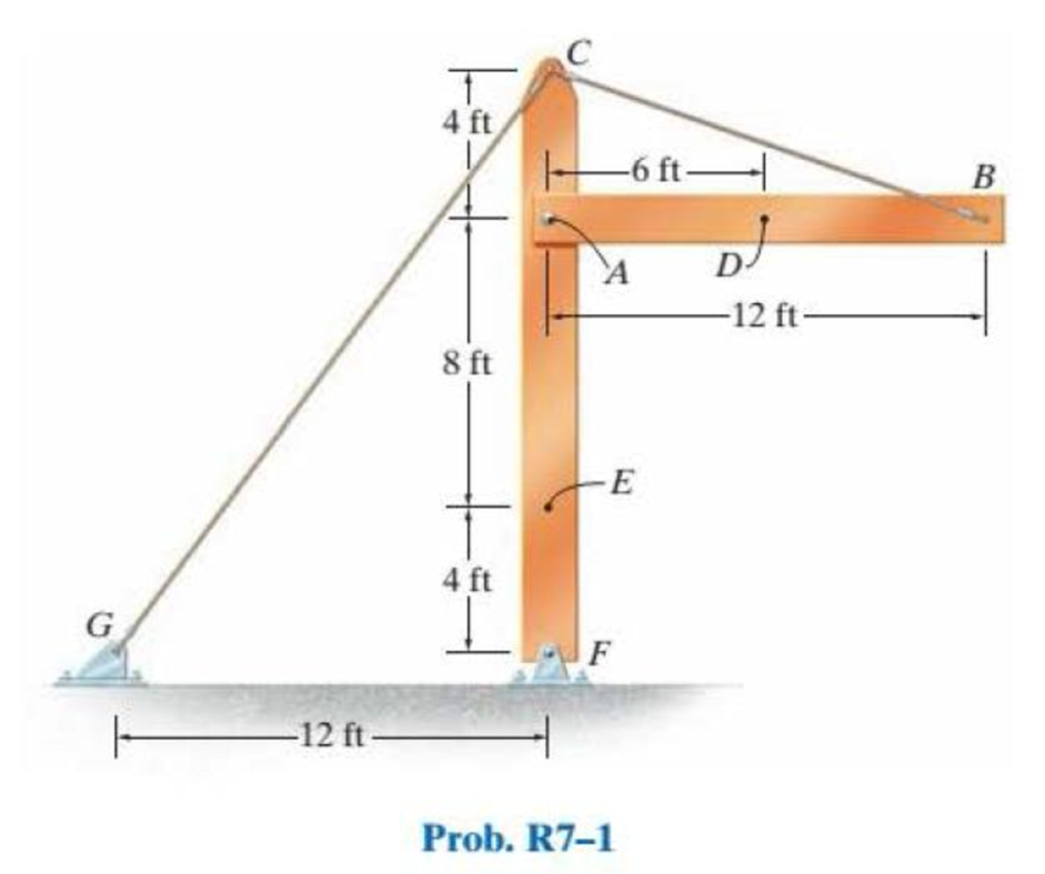
Find the resultant internal loadings acting on cross sections located at D and E.
Answer to Problem 1RP
The resultant internal loadings at cross section at D are
The resultant internal loadings at cross section at E are
Explanation of Solution
Given information:
The beam AB is pin supported at A and supported by a cable BC.
The weight of the beam AB is
The weight of the column FC is
Calculation:
Find the loading at the center of the beam AB
Substitute
Convert the unit from lb to kip.
Sketch the Free Body Diagram of the beam AB shown in Figure 1.
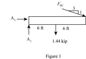
Refer to Figure 1.
Find the angle of cable BC to the horizontal
Find the tension in cable BC as shown below.
Take moment about A is Equal to zero.
Find the support reaction at A as shown below.
Apply the Equations of Equilibrium as shown below.
Summation of forces along horizontal direction is Equal to zero.
Summation of forces along vertical direction is Equal to zero.
Find the loading at the center of the beam AD
Substitute
Convert the unit from lb to kip.
Sketch the Free Body Diagram of the section for point D as shown in Figure 2.
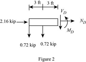
Refer to Figure 2.
Find the internal loadings as shown below.
Apply the Equations of Equilibrium as shown below.
Summation of forces along horizontal direction is Equal to zero.
Summation of forces along vertical direction is Equal to zero.
Take moment about D is Equal to zero.
Hence, the resultant internal loadings at cross section at D are
Find the loading at the center of the column FC
Substitute
Convert the unit from lb to kip.
Sketch the Free Body Diagram of the beam FC shown in Figure 3.
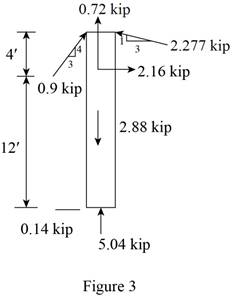
Refer to Figure 3.
Find the angle of cable CG to the horizontal.
Find the tension in cable CG as shown below.
Summation of forces along horizontal direction is Equal to zero.
Find the loading at the center of the column FE
Substitute
Convert the unit from lb to kip.
Sketch the Free Body Diagram of the section for point E as shown in Figure 4.
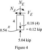
Refer to Figure 4.
Find the internal loadings as shown below.
Apply the Equations of Equilibrium as shown below.
Summation of forces along horizontal direction is Equal to zero.
Summation of forces along vertical direction is Equal to zero.
Take moment about E is Equal to zero.
Therefore, the resultant internal loadings at cross section at E are
Want to see more full solutions like this?
Chapter 7 Solutions
Statics and Mechanics of Materials (5th Edition)
Additional Engineering Textbook Solutions
Java: An Introduction to Problem Solving and Programming (8th Edition)
Fluid Mechanics: Fundamentals and Applications
Mechanics of Materials (10th Edition)
Elementary Surveying: An Introduction To Geomatics (15th Edition)
Starting Out with Programming Logic and Design (5th Edition) (What's New in Computer Science)
Computer Science: An Overview (13th Edition) (What's New in Computer Science)


- I have Euler parameters that describe the orientation of N relative to Q, e = -0.7071*n3, e4 = 0.7071. I have Euler parameters that describe the orientation of U relative to N, e = -1/sqrt(3)*n1, e4 = sqrt(2/3). After using euler parameter rule of successive rotations, I get euler parameters that describe the orientation of U relative to Q, e = -0.4082*n1 - 0.4082*n2 - 0.5774*n3. I need euler parameters that describe the orientation of U relative to Q in vector basis of q instead of n. How do I get that?arrow_forwardDescribe at least 4 processes in engineering where control charts are (or should be) appliedarrow_forwardDescribe at least two (2) processes where control charts are (or should be) applied.arrow_forward
- Problem 3: A cube-shaped spacecraft is in a circular Earth orbit. Let N (n,) be inertial and the spacecraft is denoted S (ŝ₁). The spacecraft is described such that ¯½º = J ŝ₁ŝ₁ + J ŝ₂§₂ + J §¸Ŝ3 Location of the spacecraft in the orbit is determined by the orbit-fixed unit vectors ê, that are oriented by the angle (Qt), where is a constant angular rate. 52 €3 3> 2t 55 Λ Из At the instant when Qt = 90°, the spacecraft S is oriented relative to the orbit such that 8₁ = 0° Space-three 1-2-3 angles 0₂ = 60° and ES = $₂ rad/s 0₁ = 135° (a) At this instant, determine the direction cosine matrix that describes the orientation of the spacecraft with respect to the inertial frame N.arrow_forwardThis problem illustrates that the factor of safety for a machine element depends on the particular point selected for analysis. Here you are to compute factors of safety, based upon the distortion-energy theory, for stress elements at A and B of the member shown in the figure. This bar is made of AISI 1006 cold-drawn steel and is loaded by the forces F = 1.100 kN, P = 8.00 kN, and T = 50.00 N-m. Given: Sy = 280 MPa. B -100 mm- 15-mm D. a) Determine the value of the axial stress at point B. b) Determine the value of the shear stress at point B. c) Determine the value of the Von Mises stress at point B. P Farrow_forwardA piston-cylinder device initially contains 0.08 m^3 of nitrogen gas at 130 kPa and 170°C. The nitrogen is expanded to a pressure of 80 kPa via isentropic expansion. Determine the final temperature and the boundary work done by the system during this process.arrow_forward
- A Carnot (ideal) heat pump is to be used to heat a house and maintain it at 22°C in winter. On a day when the average outdoor temperature remains at about 0°C, the house is estimated to lose heat at a rate of 65,000 kJ/h. If the heat pump consumes 6 kW of power while operating, determine: (a) how long the heat pump ran on that day (b) the total heating costs, assuming an average price of 11¢/kWh for electricity (c) the heating cost for the same day if an 85% efficient electric furnace is used instead of a heat pump.arrow_forwardFrom the information in the image, I needed to find the orientation of U relative to Q in vector basis q_hat. I transformed the euler angle/axis representation to euler parameters. Then I got its conjugate in order to get the euler parameter in N frame relative to Q. The problem gave the euler angle/axis representation in Q frame relative to N, so I needed to find the conjugate. Then I used the euler parameter rule of successive rotation to find the final euler parameters that describe the orientation of U relative to Q. However that orientation is in n_hat which is the intermediate frame. How do I get the final result in q_hat?arrow_forwardA proposed method of power generation involves collecting and storing solar energy in large artificial lakes a few meters deep, called solar ponds. Solar energy is absorbed by all parts of the pond, and the water temperature rises everywhere. The top part of the pond, however, loses much of the heat it absorbs to the atmosphere, and as a result, the cool surface water serves as insulation for the bottom part of the pond and helps trap the energy there. Usually, salt is planted at the bottom of the pond to prevent the rise of this hot water to the top. A heat engine that uses an organic fluid, such as alcohol, as the working fluid can be operated between the top and the bottom portions of the pond. If the water temperature is 27°C near the surface and 72°C near the bottom of the pond, determine the maximum thermal efficiency that this power plant can have. Treat the cycle as an ideal heat engine. Would a heat engine operating under these temperature conditions (27°C and 72°C) be…arrow_forward
 Elements Of ElectromagneticsMechanical EngineeringISBN:9780190698614Author:Sadiku, Matthew N. O.Publisher:Oxford University Press
 Mechanics of Materials (10th Edition)Mechanical EngineeringISBN:9780134319650Author:Russell C. HibbelerPublisher:PEARSON
 Thermodynamics: An Engineering ApproachMechanical EngineeringISBN:9781259822674Author:Yunus A. Cengel Dr., Michael A. BolesPublisher:McGraw-Hill Education
 Control Systems EngineeringMechanical EngineeringISBN:9781118170519Author:Norman S. NisePublisher:WILEY
 Mechanics of Materials (MindTap Course List)Mechanical EngineeringISBN:9781337093347Author:Barry J. Goodno, James M. GerePublisher:Cengage Learning
 Engineering Mechanics: StaticsMechanical EngineeringISBN:9781118807330Author:James L. Meriam, L. G. Kraige, J. N. BoltonPublisher:WILEY