
Statics and Mechanics of Materials (5th Edition)
5th Edition
ISBN: 9780134382593
Author: Russell C. Hibbeler
Publisher: PEARSON
expand_more
expand_more
format_list_bulleted
Concept explainers
Videos
Textbook Question
Chapter 7.2, Problem 5P
Determine the resultant internal loadings acting on the cross section at point B.
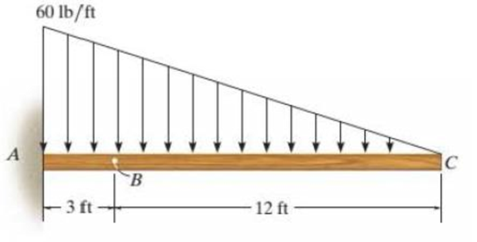
Prob. 7-5
Expert Solution & Answer
Want to see the full answer?
Check out a sample textbook solution
Students have asked these similar questions
Q6/ A helical square section spring is set inside another, the outer spring having a free
length of 35 mm greater than the inner spring. The dimensions of each spring are as
follows:
Mean diameter (mm)
Side of square section (mm)
Active turns
Outer
Inner
Spring
Spring
120
70
8
7
20
15
Determine the (1) Maximum deflection of the two springs and (2) Equivalent spring
rate of the two springs after sufficient load has been applied to deflect the outer
spring 60 mm. Use G = 83 GN/m².
Q2/ The bumper springs of a railway carriage are to be made of rectangular section wire.
The ratio of the longer side of the wire to its shorter side is 1.5, and the ratio of mean
diameter of spring to the longer side of wire is nearly equal to 6. Three such springs
are required to bring to rest a carriage weighing 25 kN moving with a velocity of
75 m/min with a maximum deflection of 200 mm. Determine the sides of the
rectangular section of the wire and the mean diameter of coils when the shorter side is
parallel to the axis of the spring. The allowable shear stress is not to exceed 300 MPa
and G = 84 kN/mm².
Q6/ A belical
11.
A load of 2 kN is dropped axially on a close coiled helical spring, from a height of 250 mm. The spring
has 20 effective turns, and it is made of 25 mm diameter wire. The spring index is 8. Find the maximum
shear stress induced in the spring and the amount of compression produced. The modulus of rigidity
for the material of the spring wire is 84 kN/mm².
[Ans. 287 MPa; 290 mm]
Chapter 7 Solutions
Statics and Mechanics of Materials (5th Edition)
Ch. 7.2 - In each case, explain how to find the resultant...Ch. 7.2 - Determine the internal normal force, shear force,...Ch. 7.2 - Determine the internal normal force, shear force,...Ch. 7.2 - Determine the internal normal force, shear force,...Ch. 7.2 - Determine the internal normal force, shear force,...Ch. 7.2 - Determine the internal normal force, shear force,...Ch. 7.2 - Determine the internal normal force, shear force,...Ch. 7.2 - The shaft is supported by a smooth thrust bearing...Ch. 7.2 - Determine the resultant internal normal and shear...Ch. 7.2 - Determine the resultant internal loadings acting...
Ch. 7.2 - The shaft is supported by a smooth thrust bearing...Ch. 7.2 - Determine the resultant internal loadings acting...Ch. 7.2 - Determine the resultant internal loadings on the...Ch. 7.2 - Determine the resultant internal loadings at cross...Ch. 7.2 - Prob. 8PCh. 7.2 - The beam supports the distributed load shown....Ch. 7.2 - The boom DF of the jib crane and the column DE...Ch. 7.2 - Determine the resultant internal loadings acting...Ch. 7.2 - Determine the resultant internal loadings acting...Ch. 7.2 - The blade of the hacksaw is subjected to a...Ch. 7.2 - The blade of the hacksaw is subjected to a...Ch. 7.2 - The beam supports the triangular distributed load...Ch. 7.2 - The beam supports the distributed load shown....Ch. 7.2 - The shaft is supported at its ends by two bearings...Ch. 7.2 - The shaft is supported at its ends by two bearings...Ch. 7.2 - The hand crank that is used in a press has the...Ch. 7.2 - Determine the resultant internal loadings acting...Ch. 7.2 - Determine the resultant internal loadings acting...Ch. 7.2 - The metal stud punch is subjected to a force of...Ch. 7.2 - Determine the resultant internal loadings acting...Ch. 7.2 - Prob. 24PCh. 7.2 - Determine the resultant internal loadings acting...Ch. 7.5 - In each case, determine the largest internal shear...Ch. 7.5 - Determine the largest internal normal force in the...Ch. 7.5 - Determine the internal normal force at section A...Ch. 7.5 - The lever is held to the fixed shaft using the pin...Ch. 7.5 - Prob. 6PPCh. 7.5 - Prob. 7FPCh. 7.5 - Determine the average normal stress on the cross...Ch. 7.5 - Prob. 9FPCh. 7.5 - If the 600-kN force acts through the centroid of...Ch. 7.5 - Prob. 11FPCh. 7.5 - Prob. 12FPCh. 7.5 - The supporting wheel on a scaffold is held in...Ch. 7.5 - Determine the largest intensity w of the uniform...Ch. 7.5 - Prob. 28PCh. 7.5 - The small block has a thickness of 0.5 in. If the...Ch. 7.5 - Prob. 30PCh. 7.5 - If the block is subjected to a centrally applied...Ch. 7.5 - Prob. 32PCh. 7.5 - The board is subjected to a tensile force of 200...Ch. 7.5 - The boom has a uniform weight of 600 lb and is...Ch. 7.5 - Determine the average normal stress in each of the...Ch. 7.5 - If the average normal stress in each of the...Ch. 7.5 - Determine the maximum average shear stress in pin...Ch. 7.5 - Prob. 38PCh. 7.5 - Prob. 39PCh. 7.5 - The column is made of concrete having a density of...Ch. 7.5 - The beam is supported by two rods AB and CD that...Ch. 7.5 - The beam is supported by two rods AB and CD that...Ch. 7.5 - Prob. 43PCh. 7.5 - The railcar docklight is supported by the...Ch. 7.5 - The plastic block is subjected to an axial...Ch. 7.5 - The two steel members are joined together using a...Ch. 7.5 - The bar has a cross-sectional area of 400(106) m2....Ch. 7.5 - Prob. 48PCh. 7.5 - The two members used in the construction of an...Ch. 7.5 - Prob. 50PCh. 7.5 - Prob. 51PCh. 7.6 - Rods AC and BC are used to suspend the 200-kg...Ch. 7.6 - The pin at A has a diameter of 0.25 in. If it is...Ch. 7.6 - Prob. 15FPCh. 7.6 - Prob. 16FPCh. 7.6 - The strut is glued to the horizontal member at...Ch. 7.6 - Prob. 18FPCh. 7.6 - Prob. 19FPCh. 7.6 - Prob. 20FPCh. 7.6 - Prob. 21FPCh. 7.6 - The pin is made of a material having a failure...Ch. 7.6 - Prob. 23FPCh. 7.6 - Prob. 24FPCh. 7.6 - Prob. 52PCh. 7.6 - Prob. 53PCh. 7.6 - The connection is made using a bolt and nut and...Ch. 7.6 - The tension member is fastened together using two...Ch. 7.6 - Prob. 56PCh. 7.6 - Prob. 57PCh. 7.6 - Determine the size of square bearing plates A and...Ch. 7.6 - Determine the maximum load P that can be applied...Ch. 7.6 - Determine the required diameter of the pins at A...Ch. 7.6 - Prob. 61PCh. 7.6 - Prob. 62PCh. 7.6 - The cotter is used to hold the two rods together...Ch. 7.6 - Determine the required diameter of the pins at A...Ch. 7.6 - The steel pipe is supported on the circular base...Ch. 7.6 - Prob. 66PCh. 7.6 - The boom is supported by the winch cable that has...Ch. 7.6 - The assembly consists of three disks A, B, and C...Ch. 7.6 - Prob. 69PCh. 7.6 - The two aluminum rods AB and AC have diameters of...Ch. 7.8 - A loading causes the member to deform into the...Ch. 7.8 - Prob. 8PPCh. 7.8 - A loading causes the wires to elongate into the...Ch. 7.8 - Prob. 10PPCh. 7.8 - Prob. 11PPCh. 7.8 - Prob. 25FPCh. 7.8 - If the force P causes the rigid arm ABC to rotate...Ch. 7.8 - The rectangular plate is deformed into the shape...Ch. 7.8 - The triangular plate is deformed into the shape...Ch. 7.8 - The square plate is deformed into the shape shown...Ch. 7.8 - Prob. 71PCh. 7.8 - Prob. 72PCh. 7.8 - If the load P on the beam causes the end C to be...Ch. 7.8 - The force applied at the handle of the rigid lever...Ch. 7.8 - The rectangular plate is subjected to the...Ch. 7.8 - Prob. 76PCh. 7.8 - Prob. 77PCh. 7.8 - Prob. 78PCh. 7.8 - Prob. 79PCh. 7.8 - Prob. 80PCh. 7.8 - Determine the shear strain xy at corners D and C...Ch. 7.8 - The material distorts into the dashed position...Ch. 7.8 - Prob. 83PCh. 7.8 - Determine the shear strain xy at comers A and B if...Ch. 7.8 - Prob. 85PCh. 7.8 - Determine the average normal strain that occurs...Ch. 7.8 - The corners of the square plate are given the...Ch. 7.8 - Prob. 88PCh. 7.8 - Prob. 89PCh. 7.8 - The triangular plate is fixed at its base, and its...Ch. 7.8 - The polysulfone block is glued at its top and...Ch. 7 - The beam AB is pin supported at A and supported by...Ch. 7 - The long bolt passes through the 30-mm-thick...Ch. 7 - Determine the required thickness of member BC and...Ch. 7 - The circular punch B exerts a force of 2 kN on the...Ch. 7 - Prob. 5RPCh. 7 - Prob. 6RPCh. 7 - The square plate is deformed into the shape shown...Ch. 7 - Prob. 8RPCh. 7 - The rubber block is fixed along edge AB, and edge...
Knowledge Booster


Learn more about
Need a deep-dive on the concept behind this application? Look no further. Learn more about this topic, mechanical-engineering and related others by exploring similar questions and additional content below.Similar questions
- Mid-Term Exam 2024/2025 Post graduate/Applied Mechanics- Metallurgy Q1/ State the type of fault in the following case, and state the structure in which it will appear. АВСАВСВАСВАСАВСАВСarrow_forwardالثانية Babakt Momentum equation for Boundary Layer S SS -Txfriction dray Momentum equation for Boundary Layer What laws are important for resolving issues 2 How to draw. 3 What's Point about this.arrow_forwardR αι g The system given on the left, consists of three pulleys and the depicted vertical ropes. Given: ri J₁, m1 R = 2r; απ r2, J2, m₂ m1; m2; M3 J1 J2 J3 J3, m3 a) Determine the radii 2 and 3.arrow_forward
- B: Solid rotating shaft used in the boat with high speed shown in Figure. The amount of power transmitted at the greatest torque is 224 kW with 130 r.p.m. Used DE-Goodman theory to determine the shaft diameter. Take the shaft material is annealed AISI 1030, the endurance limit of 18.86 kpsi and a factor of safety 1. Which criterion is more conservative? Note: all dimensions in mm. 1 AA Motor 300 Thrust Bearing Sprocket 100 9750 เอarrow_forwardQ2: The plate material of a pressure vessel is AISI 1050 QT 205 °C. The plate is rolled to a diameter of 1.2 m. The two sides of the plate are connected via a riveted joint as shown below. If the rivet material is G10500 with HB=197 and all rivet sizes M31. Find the required rivet size when the pressure vessel is subjected to an internal pressure of 500 MPa. Take safety factor = 2. 1.2m A B' A Chope olm 10.5 0.23 hopearrow_forwardContinuity equation A y x dx D T معادلة الاستمرارية Ly X Q/Prove that ди хе + ♥+ ㅇ? he me ze ོ༞“༠ ?arrow_forward
- Q Derive (continuity equation)? I want to derive clear mathematics.arrow_forwardmotor supplies 200 kW at 6 Hz to flange A of the shaft shown in Figure. Gear B transfers 125 W of power to operating machinery in the factory, and the remaining power in the shaft is mansferred by gear D. Shafts (1) and (2) are solid aluminum (G = 28 GPa) shafts that have the same diameter and an allowable shear stress of t= 40 MPa. Shaft (3) is a solid steel (G = 80 GPa) shaft with an allowable shear stress of t = 55 MPa. Determine: a) the minimum permissible diameter for aluminum shafts (1) and (2) b) the minimum permissible diameter for steel shaft (3). c) the rotation angle of gear D with respect to flange A if the shafts have the minimum permissible diameters as determined in (a) and (b).arrow_forwardFirst monthly exam Gas dynamics Third stage Q1/Water at 15° C flow through a 300 mm diameter riveted steel pipe, E-3 mm with a head loss of 6 m in 300 m length. Determine the flow rate in pipe. Use moody chart. Q2/ Assume a car's exhaust system can be approximated as 14 ft long and 0.125 ft-diameter cast-iron pipe ( = 0.00085 ft) with the equivalent of (6) regular 90° flanged elbows (KL = 0.3) and a muffler. The muffler acts as a resistor with a loss coefficient of KL= 8.5. Determine the pressure at the beginning of the exhaust system (pl) if the flowrate is 0.10 cfs, and the exhaust has the same properties as air.(p = 1.74 × 10⁻³ slug/ft³, u= 4.7 x 10⁻⁷ lb.s/ft²) Use moody chart (1) MIDAS Kel=0.3 Q3/Liquid ammonia at -20°C is flowing through a 30 m long section of a 5 mm diameter copper tube(e = 1.5 × 10⁻⁶ m) at a rate of 0.15 kg/s. Determine the pressure drop and the head losses. .μ= 2.36 × 10⁻⁴ kg/m.s)p = 665.1 kg/m³arrow_forward
arrow_back_ios
SEE MORE QUESTIONS
arrow_forward_ios
Recommended textbooks for you
 Elements Of ElectromagneticsMechanical EngineeringISBN:9780190698614Author:Sadiku, Matthew N. O.Publisher:Oxford University Press
 Mechanics of Materials (10th Edition)Mechanical EngineeringISBN:9780134319650Author:Russell C. HibbelerPublisher:PEARSON
 Thermodynamics: An Engineering ApproachMechanical EngineeringISBN:9781259822674Author:Yunus A. Cengel Dr., Michael A. BolesPublisher:McGraw-Hill Education
 Control Systems EngineeringMechanical EngineeringISBN:9781118170519Author:Norman S. NisePublisher:WILEY
 Mechanics of Materials (MindTap Course List)Mechanical EngineeringISBN:9781337093347Author:Barry J. Goodno, James M. GerePublisher:Cengage Learning
 Engineering Mechanics: StaticsMechanical EngineeringISBN:9781118807330Author:James L. Meriam, L. G. Kraige, J. N. BoltonPublisher:WILEY
Elements Of Electromagnetics
Mechanical Engineering
ISBN:9780190698614
Author:Sadiku, Matthew N. O.
Publisher:Oxford University Press
Mechanics of Materials (10th Edition)
Mechanical Engineering
ISBN:9780134319650
Author:Russell C. Hibbeler
Publisher:PEARSON
Thermodynamics: An Engineering Approach
Mechanical Engineering
ISBN:9781259822674
Author:Yunus A. Cengel Dr., Michael A. Boles
Publisher:McGraw-Hill Education
Control Systems Engineering
Mechanical Engineering
ISBN:9781118170519
Author:Norman S. Nise
Publisher:WILEY
Mechanics of Materials (MindTap Course List)
Mechanical Engineering
ISBN:9781337093347
Author:Barry J. Goodno, James M. Gere
Publisher:Cengage Learning
Engineering Mechanics: Statics
Mechanical Engineering
ISBN:9781118807330
Author:James L. Meriam, L. G. Kraige, J. N. Bolton
Publisher:WILEY
Types Of loads - Engineering Mechanics | Abhishek Explained; Author: Prime Course;https://www.youtube.com/watch?v=4JVoL9wb5yM;License: Standard YouTube License, CC-BY