
MECHANICS OF MATERIAL IN SI UNITS
10th Edition
ISBN: 9781292178202
Author: HIBBELER
Publisher: PEARSON
expand_more
expand_more
format_list_bulleted
Videos
Textbook Question
Chapter 7.5, Problem 7.67P
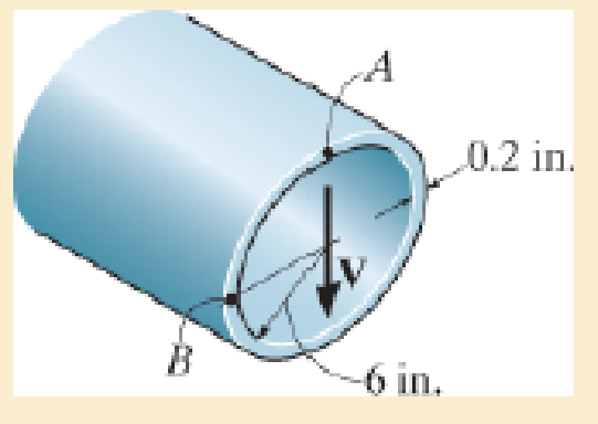
The pipe is subjected to a shear force of V=8 kip. Determine the shear flow in the pipe at points A and B.
Expert Solution & Answer
Want to see the full answer?
Check out a sample textbook solution
Students have asked these similar questions
The bevel gear shown in is subjected to the force F which is caused
from contact with another gear.
Part A
F (201+8j 15k) N
40 mm
Determine the moment of this force about the y axis of the gear shaft.
Express your answer with the appropriate units.
My =
Value
Submit
Request Answer
?
Units
30 mm
Consider the beam in.
Part A
1.5 ft
200 lb
200lb
2 ft
30°
1.25 ft
30°
If F 90 lb, determine the resultant couple moment.
=
Express your answer in pound-feet to three significant figures. Assume the positive direction is counterclockwise.
ΑΣΦ
vec
MR =
Submit
Request Answer
?
lb.ft
4. An operating parameter often used by power plant engineers is the heat rate. The heat rate is
defined as,
HR
Qbioler
Wnet
where Qbioler is the heat transfer rate (Btu/h) to the water in the boiler due to the combustion of a
fuel and Wnet is the net power (kW) delivered by the plant. In comparison, the thermal efficiency
of the power plant is defined as,
nth
Wnet
Qbioler
where the numerator and denominator have the same units. Consider a power plant that is
delivering 1000 MW of power while utilizing a heat transfer rate of 3570 MW at the boiler.
Determine the heat rate and thermal efficiency of this power plant.
Chapter 7 Solutions
MECHANICS OF MATERIAL IN SI UNITS
Ch. 7.2 - In each case, calculate the value of Q and t that...Ch. 7.2 - If the beam is subjected to a shear force of V =...Ch. 7.2 - Determine the shear stress at points A and B if...Ch. 7.2 - Determine the absolute maximum shear stress in the...Ch. 7.2 - If the beam is subjected to a shear force of V =20...Ch. 7.2 - If the beam is made from four plates and subjected...Ch. 7.2 - If the wide-flange beam is subjected to a shear of...Ch. 7.2 - If the wide-flange beam is subjected to a shear of...Ch. 7.2 - If the wide-flange beam is subjected to a shear of...Ch. 7.2 - If the beam is subjected to a shear of V = 30 kN,...
Ch. 7.2 - If the wide-flange beam is subjected to a shear of...Ch. 7.2 - The wood beam has an allowable shear stress of...Ch. 7.2 - The shaft is supported by a thrust bearing at A...Ch. 7.2 - The shaft is supported by a thrust bearing at A...Ch. 7.2 - Determine the largest shear force V that the...Ch. 7.2 - If the applied shear force V = 18 kip, determine...Ch. 7.2 - The overhang beam is subjected to the uniform...Ch. 7.2 - The beam is made from a polymer and is subjected...Ch. 7.2 - Determine the maximum shear stress in the strut if...Ch. 7.2 - Determine the maximum shear force V that the strut...Ch. 7.2 - Sketch the intensity of the shear-stress...Ch. 7.2 - Plot the shear-stress distribution over the cross...Ch. 7.2 - If the beam is subjected to a shear of V=15 kN,...Ch. 7.2 - If the wide-flange beam is subjected to a shear of...Ch. 7.2 - If the wide-flange beam is subjected to a shear of...Ch. 7.2 - Determine the length of the cantilevered beam so...Ch. 7.2 - If the beam is made from wood having an allowable...Ch. 7.2 - Determine the largest intensity w of the...Ch. 7.2 - If w=800 lb/ft, determine the absolute maximum...Ch. 7.2 - Determine the shear stress at point B on the web...Ch. 7.2 - Determine the maximum shear stress acting at...Ch. 7.2 - Railroad ties must be designed to resist large...Ch. 7.2 - The beam is slit longitudinally along both sides....Ch. 7.2 - The beam is to be cut longitudinally along both...Ch. 7.2 - The composite beam is constructed from wood and...Ch. 7.2 - The beam has a rectangular cross section and is...Ch. 7.2 - The beam in Fig.6-48f is subjected to a fully...Ch. 7.3 - The two identical boards are bolted together to...Ch. 7.3 - Two identical 20-mm-thick plates are bolted to the...Ch. 7.3 - The boards are bolted together to form the...Ch. 7.3 - The boards are bolted together to form the...Ch. 7.3 - The beam is constructed from two boards fastened...Ch. 7.3 - The beam is constructed from two boards fastened...Ch. 7.3 - The beam is constructed from three boards. If it...Ch. 7.3 - The beam is constructed from three boards....Ch. 7.3 - The double T-beam is fabricated by welding the...Ch. 7.3 - The double T-beam is fabricated by welding the...Ch. 7.3 - The beam is constructed from three boards....Ch. 7.3 - A beam is constructed from three boards bolted...Ch. 7.3 - The simply supported beam is built up from three...Ch. 7.3 - The simply supported beam is built up from three...Ch. 7.3 - The T-beam is constructed as shown. If each nail...Ch. 7.3 - The box beam is constructed from four boards that...Ch. 7.3 - The box beam is constructed from four boards that...Ch. 7.3 - The member consists of two plastic channel strips...Ch. 7.3 - The member consists of two plastic channel strips...Ch. 7.3 - The beam is made from four boards nailed together...Ch. 7.3 - The beam is made from three polystyrene strips...Ch. 7.5 - A shear force of V=300 kN is applied to the box...Ch. 7.5 - A shear force of V=450 kN is applied to the box...Ch. 7.5 - A shear force of V = 18 kN is applied to the box...Ch. 7.5 - A shear force of V = 18 kN is applied to the box...Ch. 7.5 - The aluminum strut is 10 mm thick and has the...Ch. 7.5 - The aluminum strut is 10 mm thick and has the...Ch. 7.5 - The beam is subjected to a shear force of V=50...Ch. 7.5 - The beam is subjected to a shear force of V=50...Ch. 7.5 - The H-beam is subjected to a shear of V=80 kN...Ch. 7.5 - The H-beam is subjected to a shear of V=80 kN...Ch. 7.5 - The built-up beam is formed by welding together...Ch. 7.5 - The assembly is subjected to a vertical shear of V...Ch. 7.5 - The box girder is subjected to a shear of V=15 kN....Ch. 7.5 - Determine the location e of the shear center,...Ch. 7.5 - Determine the location e of the shear center,...Ch. 7.5 - The beam supports a vertical shear of V=7 kip....Ch. 7.5 - The stiffened beam is constructed from plates...Ch. 7.5 - The pipe is subjected to a shear force of V=8 kip....Ch. 7.5 - Determine the location e of the shear center,...Ch. 7.5 - A thin plate of thickness t is bent to form the...Ch. 7.5 - Determine the location e of the shear center,...Ch. 7 - The beam is fabricated from four boards nailed...Ch. 7 - The T-beam is subjected to a shear of V = 150 kN....Ch. 7 - The member is subject to a shear force of V = 2...Ch. 7 - Determine the shear stress at points B and C on...Ch. 7 - Determine the maximum shear stress acting at...
Knowledge Booster


Learn more about
Need a deep-dive on the concept behind this application? Look no further. Learn more about this topic, mechanical-engineering and related others by exploring similar questions and additional content below.Similar questions
- The shaft shown in the sketch is subjected to tensile torsional and bending loads Determine the principal stresses at the location of stress concentration ✓ D=45MR F=3MM 1000-M 1000N チ d=30mm 500N 150 мм MM- 120 MA-arrow_forwardcalculate moment of inertia of this tapered beam structurearrow_forwardThe system shown below is in statics equilibrium. Cable OB lies in the xy plane and makes a 30° angle with the positive x-axis. Cable OA lies along the negative y-axis. If the weight of the load being supported is 100 lb, determine the magnitude of the forces in all four cables: OA, OB, OC, and OD.arrow_forward
- This is a mechanics/statics problem involving finding internal reactions, V(x) and M(x). Please refer to image for details. I'm not sure about where to take cuts and how to formulate the equations as a function of x. For my support Reactions I got Ay = 1008.33 lb, By = 1416.67 lb and Cy = 175 lb. and for the first cut V(x) = 1008.33 -250(x) and M(x) = 1008.33x - 125x^2. I'm struggling with the equations for the 2nd and 3rd cut.arrow_forwardAs shown in the figure below, a ring is used to suspend a load and is supported by Cable OA and Spring OB. Given that the tension in Cable OA is 400 N, what is the weight of the load being supported? Assume the system is in static equilibrium.arrow_forward4. (a) State the conditions that must be met to ensure dynamic balance is achieved for long rotors. (b) A rotor carries three out-of-balance discs in planes A, B and C as shown in Figure 4. The out-of- balance mass x radius products of the rotor discs are tabulated in Table 4. The shaft is to be dynamically balanced by adding balancing masses in planes P and Q, spaced along the shaft at a distance da = 800 mm. Determine the magnitude mara and angular position of the balancing mass x radius product that must be added to plane Q. MBB Ов θε mdc Мага End View on Plane P P MBB MATA dA dB dc do Figure 4 moc Table 4 MATA = 0.6 kg mm 6A = 0° d₁ = 200 mm mers = 0.2 kg mm 6g = 45° dB = 400 mm mcrc = 0.4 kg mm Bc=240° dc = 600 mm Ans. (b) = 110.5°, moro = 0.2 kg mmarrow_forward
- Need help in adding demensioning am am so confusedarrow_forwardComplete the following activity. Save as .pdf and upload to the assignment to the dropbox. 口 Use the general dimensioning symbols to correctly specify the following requirements on the drawing above.arrow_forwardplease solve and show workarrow_forward
- Water is boiling in a 25 cm diameter aluminum pan (k=237 W/mK) at 95 degrees C. Heat is transferred steadily to the boiling water in the pan through its .5 cm thick flat bottom at a rate of 800 W. if the inner surface temp of the bottom of the pan is 108 degrees C determine the boiling heat transfer coefficent on the inner surface of the pan and the outer surface temp of the bottom of the pan.arrow_forwardplease solve and show workarrow_forwardplease solve and show workarrow_forward
arrow_back_ios
SEE MORE QUESTIONS
arrow_forward_ios
Recommended textbooks for you
 International Edition---engineering Mechanics: St...Mechanical EngineeringISBN:9781305501607Author:Andrew Pytel And Jaan KiusalaasPublisher:CENGAGE L
International Edition---engineering Mechanics: St...
Mechanical Engineering
ISBN:9781305501607
Author:Andrew Pytel And Jaan Kiusalaas
Publisher:CENGAGE L
Everything About TRANSVERSE SHEAR in 10 Minutes!! - Mechanics of Materials; Author: Less Boring Lectures;https://www.youtube.com/watch?v=4x0E9yvzfCM;License: Standard Youtube License