
MECHANICS OF MATERIAL IN SI UNITS
10th Edition
ISBN: 9781292178202
Author: HIBBELER
Publisher: PEARSON
expand_more
expand_more
format_list_bulleted
Videos
Textbook Question
Chapter 7.3, Problem 7.37P
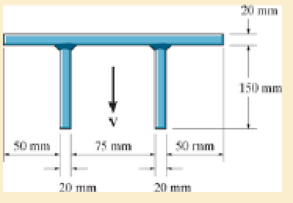
The double T-beam is fabricated by welding the three plates together as shown. If the weld can resist a shear stress τallow = 90 MPa, determine the maximum shear V that can be applied to the beam.
Probs. 7–36/37
Expert Solution & Answer
Want to see the full answer?
Check out a sample textbook solution
Students have asked these similar questions
Three alternatives are being considered for an air cleaning system. All three systems have a lifeof 10 years with no salvage value. System A has an initial cost of $29,000. During the first fiveyears of operation, the annual costs to operate system A are $5,000. During the second five years,the annual cost of system A increases to $16,000. System B has an initial cost of $43,000. Theannual cost to operate system B is $4,000, however, after the first year, this cost increases by$1,600 per year. System C has an initial cost of $58,000 with an annual cost of $2,400. System Crequires two upgrades: one during year 4 which costs $6,000, and the other during year 8 whichcosts $3,000. The MARR for this project is 17%. Determine which air cleaning system should beinstalled based on an economic analysis.
Show all work as much as you can and box out answers
Show as much work as possible and box out answers please
Chapter 7 Solutions
MECHANICS OF MATERIAL IN SI UNITS
Ch. 7.2 - In each case, calculate the value of Q and t that...Ch. 7.2 - If the beam is subjected to a shear force of V =...Ch. 7.2 - Determine the shear stress at points A and B if...Ch. 7.2 - Determine the absolute maximum shear stress in the...Ch. 7.2 - If the beam is subjected to a shear force of V =20...Ch. 7.2 - If the beam is made from four plates and subjected...Ch. 7.2 - If the wide-flange beam is subjected to a shear of...Ch. 7.2 - If the wide-flange beam is subjected to a shear of...Ch. 7.2 - If the wide-flange beam is subjected to a shear of...Ch. 7.2 - If the beam is subjected to a shear of V = 30 kN,...
Ch. 7.2 - If the wide-flange beam is subjected to a shear of...Ch. 7.2 - The wood beam has an allowable shear stress of...Ch. 7.2 - The shaft is supported by a thrust bearing at A...Ch. 7.2 - The shaft is supported by a thrust bearing at A...Ch. 7.2 - Determine the largest shear force V that the...Ch. 7.2 - If the applied shear force V = 18 kip, determine...Ch. 7.2 - The overhang beam is subjected to the uniform...Ch. 7.2 - The beam is made from a polymer and is subjected...Ch. 7.2 - Determine the maximum shear stress in the strut if...Ch. 7.2 - Determine the maximum shear force V that the strut...Ch. 7.2 - Sketch the intensity of the shear-stress...Ch. 7.2 - Plot the shear-stress distribution over the cross...Ch. 7.2 - If the beam is subjected to a shear of V=15 kN,...Ch. 7.2 - If the wide-flange beam is subjected to a shear of...Ch. 7.2 - If the wide-flange beam is subjected to a shear of...Ch. 7.2 - Determine the length of the cantilevered beam so...Ch. 7.2 - If the beam is made from wood having an allowable...Ch. 7.2 - Determine the largest intensity w of the...Ch. 7.2 - If w=800 lb/ft, determine the absolute maximum...Ch. 7.2 - Determine the shear stress at point B on the web...Ch. 7.2 - Determine the maximum shear stress acting at...Ch. 7.2 - Railroad ties must be designed to resist large...Ch. 7.2 - The beam is slit longitudinally along both sides....Ch. 7.2 - The beam is to be cut longitudinally along both...Ch. 7.2 - The composite beam is constructed from wood and...Ch. 7.2 - The beam has a rectangular cross section and is...Ch. 7.2 - The beam in Fig.6-48f is subjected to a fully...Ch. 7.3 - The two identical boards are bolted together to...Ch. 7.3 - Two identical 20-mm-thick plates are bolted to the...Ch. 7.3 - The boards are bolted together to form the...Ch. 7.3 - The boards are bolted together to form the...Ch. 7.3 - The beam is constructed from two boards fastened...Ch. 7.3 - The beam is constructed from two boards fastened...Ch. 7.3 - The beam is constructed from three boards. If it...Ch. 7.3 - The beam is constructed from three boards....Ch. 7.3 - The double T-beam is fabricated by welding the...Ch. 7.3 - The double T-beam is fabricated by welding the...Ch. 7.3 - The beam is constructed from three boards....Ch. 7.3 - A beam is constructed from three boards bolted...Ch. 7.3 - The simply supported beam is built up from three...Ch. 7.3 - The simply supported beam is built up from three...Ch. 7.3 - The T-beam is constructed as shown. If each nail...Ch. 7.3 - The box beam is constructed from four boards that...Ch. 7.3 - The box beam is constructed from four boards that...Ch. 7.3 - The member consists of two plastic channel strips...Ch. 7.3 - The member consists of two plastic channel strips...Ch. 7.3 - The beam is made from four boards nailed together...Ch. 7.3 - The beam is made from three polystyrene strips...Ch. 7.5 - A shear force of V=300 kN is applied to the box...Ch. 7.5 - A shear force of V=450 kN is applied to the box...Ch. 7.5 - A shear force of V = 18 kN is applied to the box...Ch. 7.5 - A shear force of V = 18 kN is applied to the box...Ch. 7.5 - The aluminum strut is 10 mm thick and has the...Ch. 7.5 - The aluminum strut is 10 mm thick and has the...Ch. 7.5 - The beam is subjected to a shear force of V=50...Ch. 7.5 - The beam is subjected to a shear force of V=50...Ch. 7.5 - The H-beam is subjected to a shear of V=80 kN...Ch. 7.5 - The H-beam is subjected to a shear of V=80 kN...Ch. 7.5 - The built-up beam is formed by welding together...Ch. 7.5 - The assembly is subjected to a vertical shear of V...Ch. 7.5 - The box girder is subjected to a shear of V=15 kN....Ch. 7.5 - Determine the location e of the shear center,...Ch. 7.5 - Determine the location e of the shear center,...Ch. 7.5 - The beam supports a vertical shear of V=7 kip....Ch. 7.5 - The stiffened beam is constructed from plates...Ch. 7.5 - The pipe is subjected to a shear force of V=8 kip....Ch. 7.5 - Determine the location e of the shear center,...Ch. 7.5 - A thin plate of thickness t is bent to form the...Ch. 7.5 - Determine the location e of the shear center,...Ch. 7 - The beam is fabricated from four boards nailed...Ch. 7 - The T-beam is subjected to a shear of V = 150 kN....Ch. 7 - The member is subject to a shear force of V = 2...Ch. 7 - Determine the shear stress at points B and C on...Ch. 7 - Determine the maximum shear stress acting at...
Knowledge Booster


Learn more about
Need a deep-dive on the concept behind this application? Look no further. Learn more about this topic, mechanical-engineering and related others by exploring similar questions and additional content below.Similar questions
- on-the-job conditions. 9 ±0.2- 0.5 M Application questions 1-7 refer to the drawing above. 1. What does the flatness tolerance labeled "G" apply to? Surface F A. B. Surfaces E and F C. Surfaces D, E, H, and I D. The derived median plane of 12 +0.2 0.5 0.5 CF) 20 ±0.2 0.1 7. O 12 ±0.2- H 0.3 ASME Y14.5-2009arrow_forwardelements, each with a length of 1 m. Determine the temperature on node 1, 2, 3, 4. 3. Solve the strong form analytically (you may choose Maple, MATLAB or Mathematica to help you solve this ODE). Compare the FE approximate temperature distribution through the block against the analytical solution. 1 (1) 200 °C 2 (2) 3 m 3 (3)arrow_forwardCompute the horizontal and vertical components of the reaction at the pin A. B A 30° 0.75 m 1 m 60 N 0.5 m 90 N-marrow_forward
- A particle is held and then let go at the edge of a circular shaped hill of radius R = shown below. The angular motion of the particle is governed by the following ODE: + 0.4 02 - 2 cos 0 + 0.8 sin 0 = 0 where is the angle in rad measured from the top (CCW: +), ė 5m, as = wis the velocity in rad/s, ==a is the angular acceleration in rad/s². Use MATLAB to numerically integrate the second order ODE and predict the motion of the particle. (a) Plot and w vs. time (b) How long does it take for the particle to fall off the ring at the bottom? (c) What is the particle speed at the bottom. Hint v = Rw. in de all questions the particles inside the tube. /2/07/25 Particle R 0 0 R eled witharrow_forwardIf FA = 40 KN and FB = 35 kN, determine the magnitude of the resultant force and specify the location of its point of application (x, y) on the slab. 30 kN 0.75 m 90 kN FB 2.5 m 20 kN 2.5 m 0.75 m FA 0.75 m 3 m 3 m 0.75 marrow_forwardThe elastic bar from Problem 1 spins with angular velocity ω about an axis, as shown in the figure below. The radial acceleration at a generic point x along the bar is a(x) = ω 2 x. Under this radial acceleration, the bar stretches along x with displacement function u(x). The displacement u(x) is governed by the following equations: ( d dx (σ(x)) + ρa(x) = 0 PDE σ(x) = E du dx Hooke’s law (2) where σ(x) is the axial stress in the rod, ρ is the mass density, and E is the (constant) Young’s modulus. The bar is pinned on the rotation axis at x = 0 and it is also pinned at x = L. Determine:1. Appropriate BCs for this physical problem.2. The displacement function u(x).3. The stress function σ(x).arrow_forward
- The heated rod from Problem 3 is subject to a volumetric heatingh(x) = h0xLin units of [Wm−3], as shown in the figure below. Under theheat supply the temperature of the rod changes along x with thetemperature function T(x). The temperature T(x) is governed by thefollowing equations:(−ddx (q(x)) + h(x) = 0 PDEq(x) = −kdTdx Fourier’s law of heat conduction(4)where q(x) is the heat flux through the rod and k is the (constant)thermal conductivity. Both ends of the bar are in contact with a heatreservoir at zero temperature. Determine:1. Appropriate BCs for this physical problem.2. The temperature function T(x).3. The heat flux function q(x).arrow_forwardA heated rod of length L is subject to a volumetric heating h(x) = h0xLinunits of [Wm−3], as shown in the figure below. Under the heat supply thetemperature of the rod changes along x with the temperature functionT(x). The temperature T(x) is governed by the following equations:(−ddx (q(x)) + h(x) = 0 PDEq(x) = −kdTdx Fourier’s law of heat conduction(3)where q(x) is the heat flux through the rod and k is the (constant)thermal conductivity. The left end of the bar is in contact with a heatreservoir at zero temperature, while the right end of the bar is thermallyinsulated. Determine:1. Appropriate BCs for this physical problem.2. The temperature function T(x).3. The heat flux function q(x).arrow_forwardCalculate the mean piston speed (in mph) for a Formula 1 engine running at 14,750 rpm with a bore of 80mm and a stroke of 53mm. Estimate the average acceleration imparted on the piston as it moves from TDC to 90 degrees ATDCarrow_forward
- Calculate the compression ratio of an engine with a stroke of 4.2inches a bore of 4.5 inches and a clearance volume of 6.15 cubic inches. Discuss whether or not this is a realistic compression ratio for a street engine and what octane rating of fuel it would need to run correctlyarrow_forwardDraw the free-body diagram for the pinned assembly shown. Find the magnitude of the forces acting on each member of the assembly. 1500 N 1500 N C 45° 45° 45° 45° 1000 mmarrow_forwardAn elastic bar of length L spins with angular velocity ω about an axis, as shown in the figure below. The radial acceleration at a generic point x along the bar is a(x) = ω 2 x. Due to this radial acceleration, the bar stretches along x with displacement function u(x). The displacement u(x) is governed by the following equations: ( d dx (σ(x)) + ρa(x) = 0 PDE σ(x) = E du dx Hooke’s law (1) where σ(x) is the axial stress in the rod, ρ is the mass density, and E is the (constant) Young’s modulus. The bar is pinned on the rotation axis at x = 0, and it is free at x = L. Determine:1. Appropriate BCs for this physical problem.2. The displacement function u(x).3. The stress function σ(x).arrow_forward
arrow_back_ios
SEE MORE QUESTIONS
arrow_forward_ios
Recommended textbooks for you
 Elements Of ElectromagneticsMechanical EngineeringISBN:9780190698614Author:Sadiku, Matthew N. O.Publisher:Oxford University Press
 Mechanics of Materials (10th Edition)Mechanical EngineeringISBN:9780134319650Author:Russell C. HibbelerPublisher:PEARSON
 Thermodynamics: An Engineering ApproachMechanical EngineeringISBN:9781259822674Author:Yunus A. Cengel Dr., Michael A. BolesPublisher:McGraw-Hill Education
 Control Systems EngineeringMechanical EngineeringISBN:9781118170519Author:Norman S. NisePublisher:WILEY
 Mechanics of Materials (MindTap Course List)Mechanical EngineeringISBN:9781337093347Author:Barry J. Goodno, James M. GerePublisher:Cengage Learning
 Engineering Mechanics: StaticsMechanical EngineeringISBN:9781118807330Author:James L. Meriam, L. G. Kraige, J. N. BoltonPublisher:WILEY
Elements Of Electromagnetics
Mechanical Engineering
ISBN:9780190698614
Author:Sadiku, Matthew N. O.
Publisher:Oxford University Press
Mechanics of Materials (10th Edition)
Mechanical Engineering
ISBN:9780134319650
Author:Russell C. Hibbeler
Publisher:PEARSON
Thermodynamics: An Engineering Approach
Mechanical Engineering
ISBN:9781259822674
Author:Yunus A. Cengel Dr., Michael A. Boles
Publisher:McGraw-Hill Education
Control Systems Engineering
Mechanical Engineering
ISBN:9781118170519
Author:Norman S. Nise
Publisher:WILEY
Mechanics of Materials (MindTap Course List)
Mechanical Engineering
ISBN:9781337093347
Author:Barry J. Goodno, James M. Gere
Publisher:Cengage Learning
Engineering Mechanics: Statics
Mechanical Engineering
ISBN:9781118807330
Author:James L. Meriam, L. G. Kraige, J. N. Bolton
Publisher:WILEY
Everything About TRANSVERSE SHEAR in 10 Minutes!! - Mechanics of Materials; Author: Less Boring Lectures;https://www.youtube.com/watch?v=4x0E9yvzfCM;License: Standard Youtube License