
Fundamentals of Electric Circuits
6th Edition
ISBN: 9780078028229
Author: Charles K Alexander, Matthew Sadiku
Publisher: McGraw-Hill Education
expand_more
expand_more
format_list_bulleted
Concept explainers
Videos
Textbook Question
Chapter 7.5, Problem 10PP
Find v(t) for t > 0 in the circuit of Fig. 7.44. Assume the switch has been open for a long time and is closed at t = 0. Calculate v(t) at t = 0.5.
Answer: (9.375 + 5.625 e−2t) V for all t > 0, 11.444 V.
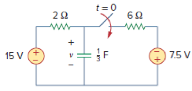
Figure 7.44
For Practice Prob. 7.10.
Expert Solution & Answer
Want to see the full answer?
Check out a sample textbook solution
Students have asked these similar questions
Q: Design of AM system
1- Draw the block diagram for AM transmitter
2- Draw the output waveform of transmitter and what is the
device measure the output?
3- Draw the spectrum frequency for the output of transmitter
4- Why we use the modulation?
Do
The following circuit is at steady state for t<0. At t=0 sec, the switch is open. Let R₁ =14 ohms, R₂=14
ohms, R3-4 ohms, C₁-1 F, Vx-16 V and Ix-7 A. Find Vc1 (0.8 sec) and voltage across resistor R3 = v(1.4 sec),
as follows:
Vc1(0) in volts=
Vc1(00) in volts=
Rth in ohms=
Vc1(t-0.8 sec) in volts=
v(t-1.4 sec) in volts=
Vx
w
t=0
The relative tolerance for this problem is 10 %.
+
www
R₂
Vit
R3
+
Vc1(t)
C₁
For the circuit shown, the switch opens at t=0 sec. Find i(t=1.5) value as follows.
Let R1-12 ohm, R₂-8 ohm, L=0.6 H, V≤1-10 V and V2-8 V, and determine:
i(0) =
A
A
i(∞0) =
Rth
=
i(1.5 sec)
Ω
A
R₁
L
i(t)
VS2
R2
w
The relative tolerance for this problem is 9 %.
+
V S1
Chapter 7 Solutions
Fundamentals of Electric Circuits
Ch. 7.2 - Refer to the circuit in Fig. 7.7. Let vC (0) = 60...Ch. 7.2 - If the switch in Fig. 7.10 opens at t = 0, find...Ch. 7.3 - Find i and vx in the circuit of Fig. 7.15. Let...Ch. 7.3 - For the circuit in Fig. 7.18, find i(t) for t 0....Ch. 7.3 - Determine i, io, and vo for all t in the circuit...Ch. 7.4 - Express the current pulse in Fig. 7.33 in terms of...Ch. 7.4 - Refer to Fig. 7.39. Express i(t) in terms of...Ch. 7.4 - If h t = 0, t0 4, 0t2 3t8, 2t6 0, t6 express h(t)...Ch. 7.4 - Practice Problem 7.9 Evaluate the following...Ch. 7.5 - Find v(t) for t 0 in the circuit of Fig. 7.44....
Ch. 7.5 - The switch in Fig. 7.47 is closed at t = 0. Find...Ch. 7.6 - The switch in Fig. 7.52 has been closed for a long...Ch. 7.6 - Switch S1 in Fig. 7.54 is closed at t = 0, and...Ch. 7.7 - For the op amp circuit in Fig. 7.56, find vo for t...Ch. 7.7 - Find v(t) and vo(t) in the op amp circuit of Fig....Ch. 7.7 - Obtain the step response vo(t) for the circuit in...Ch. 7.8 - For the circuit in Fig. 7.66, use Pspice to find...Ch. 7.8 - The switch in Fig. 7.71 was open for a long time...Ch. 7.9 - The RC circuit in Fig. 7.74 is designed to operate...Ch. 7.9 - The flash unit of a camera has a 2-mF capacitor...Ch. 7.9 - A relay has a resistance of 200 and an inductance...Ch. 7.9 - Prob. 22PPCh. 7 - An RC circuit has R = 2 and C = 4 F. The time...Ch. 7 - The time constant for an RL circuit with R = 2 ...Ch. 7 - A capacitor in an RC circuit with R = 2 and C = 4...Ch. 7 - An RL circuit has R = 2 and L = 4 H. The time...Ch. 7 - In the circuit of Fig. 7.79, the capacitor voltage...Ch. 7 - Figure 7.79 For Review Questions 7.5 and 7.6....Ch. 7 - For the circuit in Fig. 7.80, the inductor current...Ch. 7 - Figure 7.80 For Review Questions 7.7 and 7.8....Ch. 7 - If vs changes from 2 V to 4 V at t = 0, we may...Ch. 7 - The pulse in Fig. 7.116(a) can be expressed in...Ch. 7 - In the circuit shown in Fig. 7.81...Ch. 7 - Find the time constant for the RC circuit in Fig....Ch. 7 - Determine the time constant for the circuit in...Ch. 7 - The switch in Fig. 7.84 has been in position A for...Ch. 7 - Using Fig. 7.85, design a problem to help other...Ch. 7 - The switch in Fig. 7.86 has been closed for a long...Ch. 7 - Assuming that the switch in Fig. 7.87 has been in...Ch. 7 - For the circuit in Fig. 7.88, if...Ch. 7 - The switch in Fig. 7.89 opens at t = 0. Find vo...Ch. 7 - For the circuit in Fig. 7.90, find vo(t) for t 0....Ch. 7 - For the circuit in Fig. 7.91, find io for t 0....Ch. 7 - Using Fig. 7.92, design a problem to help other...Ch. 7 - In the circuit of Fig. 7.93,...Ch. 7 - Calculate the time constant of the circuit in Fig....Ch. 7 - Find the time constant for each of the circuits in...Ch. 7 - Determine the time constant for each of the...Ch. 7 - Consider the circuit of Fig. 7.97. Find vo(t) if...Ch. 7 - For the circuit in Fig. 7.98, determine vo(t) when...Ch. 7 - In the circuit of Fig. 7.99, find i(t) for t 0 if...Ch. 7 - For the circuit in Fig. 7.100, v = 90e50t V and i...Ch. 7 - In the circuit of Fig. 7.101, find the value of R...Ch. 7 - Find i(t) and v(t) for t 0 in the circuit of Fig....Ch. 7 - Consider the circuit in Fig. 7.103. Given that...Ch. 7 - Express the following signals in terms of...Ch. 7 - Design a problem to help other students better...Ch. 7 - Express the signals in Fig. 7.104 in terms of...Ch. 7 - Express v(t) in Fig. 7.105 in terms of step...Ch. 7 - Sketch the waveform represented by i(t) = [r(t) ...Ch. 7 - Sketch the following functions: (a) x(t) = 10etu(t...Ch. 7 - Prob. 30PCh. 7 - Evaluate the following integrals: (a)e4t2(t2)dt...Ch. 7 - Prob. 32PCh. 7 - The voltage across a 10-mH inductor is 45(t 2)mV....Ch. 7 - Evaluate the following derivatives: (a) ddtut1ut+1...Ch. 7 - Find the solution to the following differential...Ch. 7 - Solve for v in the following differential...Ch. 7 - A circuit is described by 4dvdt+v=10 (a) What is...Ch. 7 - A circuit is described by didt+3i=2ut Find i(t)...Ch. 7 - Calculate the capacitor voltage for t 0 and t 0...Ch. 7 - Find the capacitor voltage for t 0 and t 0 for...Ch. 7 - Using Fig. 7.108, design a problem to help other...Ch. 7 - (a) If the switch in Fig. 7.109 has been open for...Ch. 7 - Consider the circuit in Fig. 7.110. Find i(t) for...Ch. 7 - The switch in Fig. 7.111 has been in position a...Ch. 7 - Find vo in the circuit of Fig. 7.112 when vs =...Ch. 7 - Prob. 46PCh. 7 - Determine v(t) for t 0 in the circuit of Fig....Ch. 7 - Find v(t) and i(t) in the circuit of Fig. 7.115....Ch. 7 - If the waveform in Fig. 7.116(a) is applied to the...Ch. 7 - In the circuit of Fig. 7.117, find ix for t 0....Ch. 7 - Rather than applying the shortcut technique used...Ch. 7 - Using Fig. 7.118, design a problem to help other...Ch. 7 - Determine the inductor current i(t) for both t 0...Ch. 7 - Obtain the inductor current for both t 0 and t 0...Ch. 7 - Find v(t) for t 0 and t 0 in the circuit of Fig....Ch. 7 - Prob. 56PCh. 7 - Prob. 57PCh. 7 - Rework Prob. 7.17 if i(0) = 10 A and v(t) = 20u(t)...Ch. 7 - Determine the step response vo(t) to is = 6u(t) A...Ch. 7 - Find v(t) for t 0 in the circuit of Fig. 7.125 if...Ch. 7 - In the circuit in Fig. 7.126, is changes from 5 A...Ch. 7 - For the circuit in Fig. 7.127, calculate i(t) if...Ch. 7 - Obtain v(t) and i(t) in the circuit of Fig. 7.128....Ch. 7 - Determine the value of iL(t) and the total energy...Ch. 7 - If the input pulse in Fig. 7.130(a) is applied to...Ch. 7 - Using Fig. 7.131, design a problem to help other...Ch. 7 - If v(0) = 10 V, find vo(t) for t 0 in the op amp...Ch. 7 - Prob. 68PCh. 7 - For the op amp circuit in Fig. 7.134, find vo(t)...Ch. 7 - Determine vo for t 0 when vs = 20 mV in the op...Ch. 7 - For the op amp circuit in Fig. 7.136, suppose vs =...Ch. 7 - Find io in the op amp circuit in Fig. 7.137....Ch. 7 - For the op amp circuit of Fig. 7.138, let R1 = 10...Ch. 7 - Determine vo(t) for t 0 in the circuit of Fig....Ch. 7 - In the circuit of Fig. 7.140, find vo and io,...Ch. 7 - Repeat Prob. 7.49 using PSpice or MultiSim. If the...Ch. 7 - The switch in Fig. 7.141 opens at t = 0. Use...Ch. 7 - The switch in Fig. 7.142 moves from position a to...Ch. 7 - In the circuit of Fig. 7.143, determine io(t)....Ch. 7 - In the circuit of Fig. 7.144, find the value of io...Ch. 7 - Repeat Prob. 7.65 using PSpice or MultiSim. If the...Ch. 7 - In designing a signal-switching circuit, it was...Ch. 7 - Prob. 83PCh. 7 - A capacitor with a value of 10 mF has a leakage...Ch. 7 - A simple relaxation oscillator circuit is shown in...Ch. 7 - Figure 7.146 shows a circuit for setting the...Ch. 7 - A 120-V dc generator energizes a motor whose coil...Ch. 7 - The circuit in Fig. 7.148(a) can be designed as an...Ch. 7 - An RL circuit may be used as a differentiator if...Ch. 7 - An attenuator probe employed with oscilloscopes...Ch. 7 - The circuit in Fig. 7.150 is used by a biology...Ch. 7 - To move a spot of a cathode-ray tube across the...
Knowledge Booster


Learn more about
Need a deep-dive on the concept behind this application? Look no further. Learn more about this topic, electrical-engineering and related others by exploring similar questions and additional content below.Similar questions
- You must have noticed that, when a major appliance is turned on (such as an AC unit, garbage disposal, etc.), your house lights dim momentarily. This is the effect of the RL circuit formed by the inductance and resistance of the transmission line and the loads (light bulbs, appliance, etc.) In fact, even a single straight wire has inductance. The inductance (and the resistance) of a long transmission line can be problematic if the system is not properly designed. The voltage on a power transmission line is alternating current but the effect of transmission line can be simulated by a DC circuit as shown below, where R=0.005 2 /km and L=0.04 H/km representing the resistance and inductance of the transmission line per km relationship that is with the ration: L-8 R. In the circuit, Right =160 represents light bulb resistances, R₁ = 7 represents the resistance of a 'major appliance', and the switch indicates when the appliance is turn on. Alice, a newly hired engineer, needs to determine…arrow_forwardFor the circuit shown, let Let R₁-3 ohms, R2-7 ohms, C₁-2 F, VX-20 V and Ix-1 A. Calculate the capacitor voltages, as shows, at time t= (-1.3) sec and at t=1.9 sec. In particular find: V(0) = V(∞) = Rth V(t=-1.3 sec) in volts- V(t-1.9 sec) in volts- C1 HH +V(t) = - (V) (V) (S2) (V) 3 (V) Vx +1 R1 t=0 The relative tolerance for this problem is 9 %. R₂arrow_forwardIn the circuit below, the switch moves from position 1 to position 2 at t=0. Select the closest waveform which represents the inductor current: 2 R 2R V₁ t=0 0 t=0 (a) (d) t=0 (b) (e) 0 0 t=0 (c) t=0 요 (f) Note: choices are listed randomly; may not alphabetically ordered. (given during job interview question, with permission) waveform c waveform a O waveform d waveform e waveform b ○ waveform f t=0 Rarrow_forward
- Let R1-8 ohms, R₂-5 ohms, L₁-2 H, Vx=10 V, in the circuit shown, to calculate the inductor current at time t= (0.6 sec) and at t= 2 sec, as follows: i(0) = 1(00) - Rth= = i(0.6 sec) = i(2 sec) = R₁ (A) (A) (N) Vx 1=0 The relative tolerance for this problem is 9 %. (A) (A) R2 ell 4₁arrow_forwardThe following circuit is at steady state for t<0. At t=0 sec, the switch opens. Let R₁=102, R₂-12 2, R3=6 2, R4-6, C=0.9 F and V₂-14 V, and find V(t) at t =2.206 sec, as follows: V(0) = (V) V(∞0) = RTh = V(2.206) = (V) (Ω) (V) {To avoid errors, and meet allowed tolerance, carry-out your intermediate numerical values as much as possible than round only the entered values to 3 significant digits} R₁ w V (+ R₂ ww + C EV(t) R3 The relative tolerance for this problem is 10 %. Question Help: Written Example I R4 www 2=0arrow_forwardPM Mon Apr 14 la800803.us.archive.org Chapter 5 Problems 199 5-8 5-9 carry generator of Fig. 5-5. Derive the two-level Boolean expression for the output carry Cs shown in the look-ahead How many unused input combinations are there in a BCD adder? 5-10 Design a combinational circuit that generated the 9's complement of a BCD digit. 5-11 Construct a 4-digit BCD adder-subtractor using four BCD adders, as shown in Fig. 5-6, and four 9's complement circuits from Problem 5-10. Use block diagrams for each compo- nent, showing only inputs and outputs. 5-12 It is necessary to design a decimal adder for two digits represented in the excess-3 code. Show that the correction after adding the two digits with a 4-bit binary adder is as fol- lows: (a) The output carry is equal to the carry from the binary adder. = (b) If the output carry 1, then add 0011. (c) If the output carry = 0, then add 1101. Construct the decimal adder with two 4-bit adders and an inverter. 5-13 Design a combinational circuit…arrow_forward
- For the circuit shown, assume the initial capacitor voltage is V(0-) = -8 V. Then at t=0, the switch closes. Find the time at which Vc(t)-8 V. Let R₁-12 S2, C1-8 F and V₂-16 V The voltage Vc(∞ )= Time-constant T= The time at which Vc(t)-8 V ist = (V) (sec) (sec) + R1 C₁ + Vct) The relative tolerance for this problem is 10 %.arrow_forward13. Find i(t) for t > 0 in the following circuitarrow_forwardCalculate the Capacitor Voltage for t > 0 assuming the switch has been open for long time.arrow_forward
- 14. Find i(t) for t > 0 in the following circuit Note: the current source is only ON for t > 0. So, it would be an open circuit for t < 0arrow_forward10. Find v(t) for t > 0 in the following circuit. Note: the current source is only ON for t > 0. So, it would be an open circuit for t < 0arrow_forward3. Calculate the Capacitor Voltage for the t 0 for the following circuit. 302 292 12 V 4 V 3 F 2arrow_forward
arrow_back_ios
SEE MORE QUESTIONS
arrow_forward_ios
Recommended textbooks for you
 Introductory Circuit Analysis (13th Edition)Electrical EngineeringISBN:9780133923605Author:Robert L. BoylestadPublisher:PEARSON
 Delmar's Standard Textbook Of ElectricityElectrical EngineeringISBN:9781337900348Author:Stephen L. HermanPublisher:Cengage Learning
 Programmable Logic ControllersElectrical EngineeringISBN:9780073373843Author:Frank D. PetruzellaPublisher:McGraw-Hill Education
 Fundamentals of Electric CircuitsElectrical EngineeringISBN:9780078028229Author:Charles K Alexander, Matthew SadikuPublisher:McGraw-Hill Education
 Electric Circuits. (11th Edition)Electrical EngineeringISBN:9780134746968Author:James W. Nilsson, Susan RiedelPublisher:PEARSON
 Engineering ElectromagneticsElectrical EngineeringISBN:9780078028151Author:Hayt, William H. (william Hart), Jr, BUCK, John A.Publisher:Mcgraw-hill Education,
Introductory Circuit Analysis (13th Edition)
Electrical Engineering
ISBN:9780133923605
Author:Robert L. Boylestad
Publisher:PEARSON
Delmar's Standard Textbook Of Electricity
Electrical Engineering
ISBN:9781337900348
Author:Stephen L. Herman
Publisher:Cengage Learning
Programmable Logic Controllers
Electrical Engineering
ISBN:9780073373843
Author:Frank D. Petruzella
Publisher:McGraw-Hill Education
Fundamentals of Electric Circuits
Electrical Engineering
ISBN:9780078028229
Author:Charles K Alexander, Matthew Sadiku
Publisher:McGraw-Hill Education
Electric Circuits. (11th Edition)
Electrical Engineering
ISBN:9780134746968
Author:James W. Nilsson, Susan Riedel
Publisher:PEARSON
Engineering Electromagnetics
Electrical Engineering
ISBN:9780078028151
Author:Hayt, William H. (william Hart), Jr, BUCK, John A.
Publisher:Mcgraw-hill Education,
ENA 9.2(1)(En)(Alex) Sinusoids & Phasors - Explanation with Example 9.1 ,9.2 & PP 9.2; Author: Electrical Engineering Academy;https://www.youtube.com/watch?v=vX_LLNl-ZpU;License: Standard YouTube License, CC-BY
Electrical Engineering: Ch 10 Alternating Voltages & Phasors (8 of 82) What is a Phasor?; Author: Michel van Biezen;https://www.youtube.com/watch?v=2I1tF3ixNg0;License: Standard Youtube License