
Concept explainers
Videos
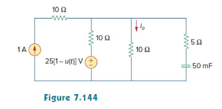
In the circuit of Fig. 7.144, find the value of io for all values of 0 < t.
Find the current
Answer to Problem 80P
The current
Explanation of Solution
Given data:
Refer to Figure 7.144 in the textbook.
The value of capacitance
The source voltage
The current source
Formula used:
Write the general expression to find the complete voltage response for an RC circuit.
Here,
Write the expression to find the time constant for an RC circuit.
Here,
C is the capacitance of the capacitor.
Write the general expression for the unit step function.
Calculation:
The given source voltage is,
Apply the unit step function in equation (3) to equation (4).
For
The given Figure 7.144 is redrawn as shown in Figure 1.
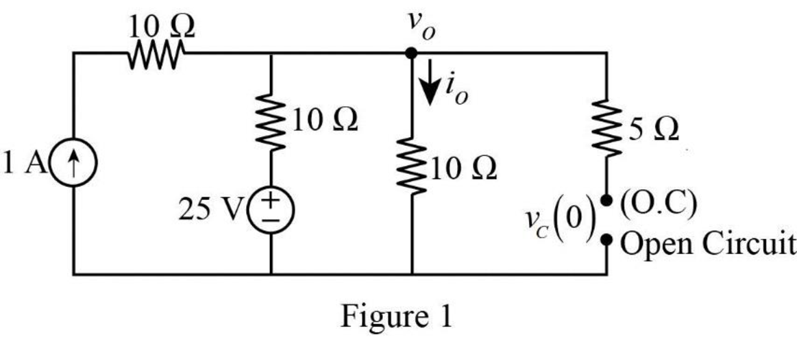
In Figure 1, the capacitor reaches steady state and it will acts as an open circuit. The initial voltage across the capacitor is denoted by
Apply Kirchhoff’s current law at node
Rearrange the equation as follows,
In Figure 1, the initial voltage across the capacitor
For
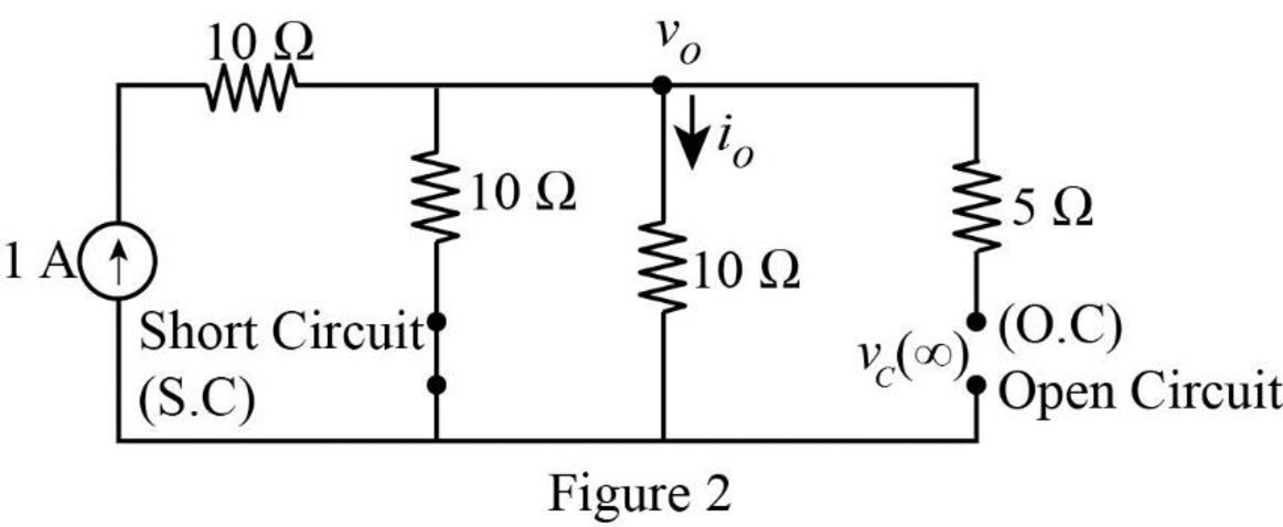
In Figure 2, the voltage source is equal to zero (or a short circuit). Now, the final voltage across the capacitor is represented by
Apply Kirchhoff’s current law at node
Rearrange the equation as follows,
In Figure 2, the final voltage across the capacitor
Figure 3 shows the Thevenin resistance at the capacitor terminal.
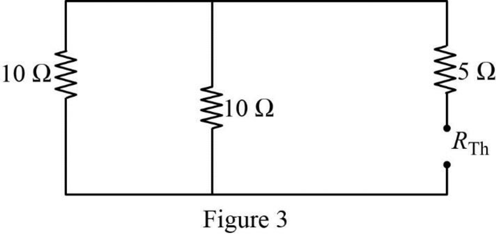
In Figure 3, the Thevenin resistance is calculated as follows.
Substitute
Substitute the units
Substitute
Figure 4 shows the modified circuit diagram.
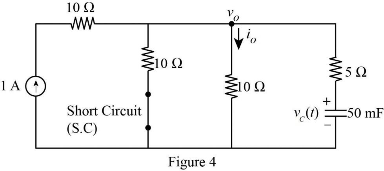
Apply Kirchhoff’s current law at node
Substitute
Reduce the equation as follows,
Therefore, the current
Substitute
Convert the unit A to mA.
Apply the unit step function in equation (3) to equation (6).
PSpice Simulation:
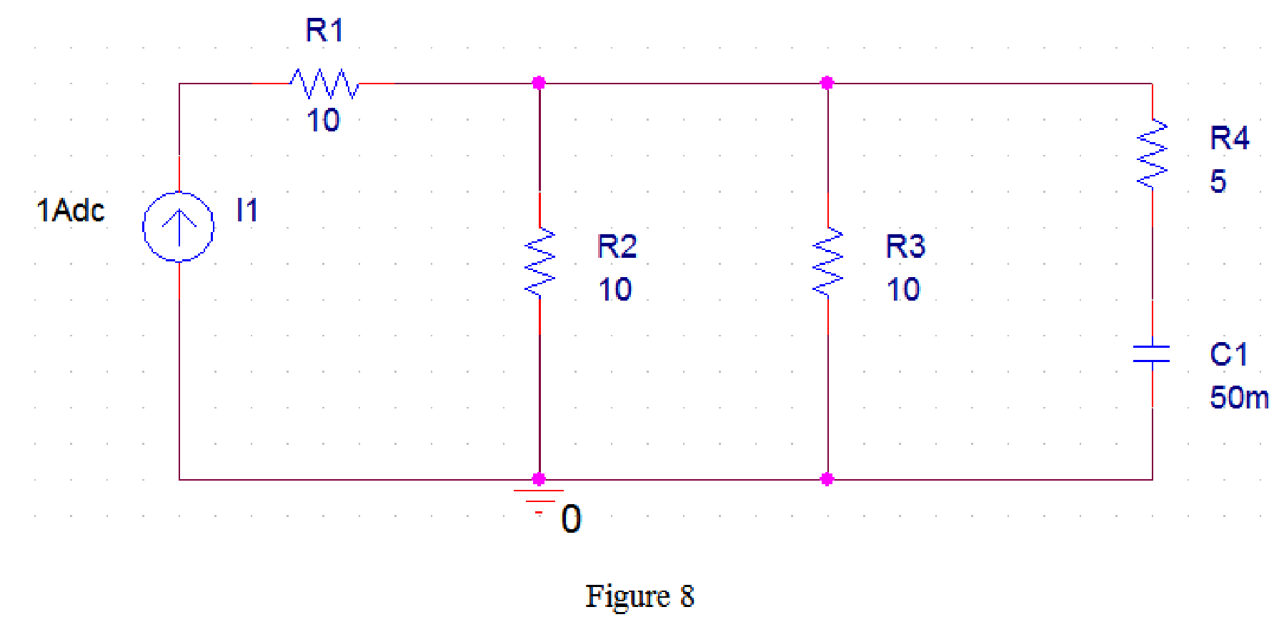
For
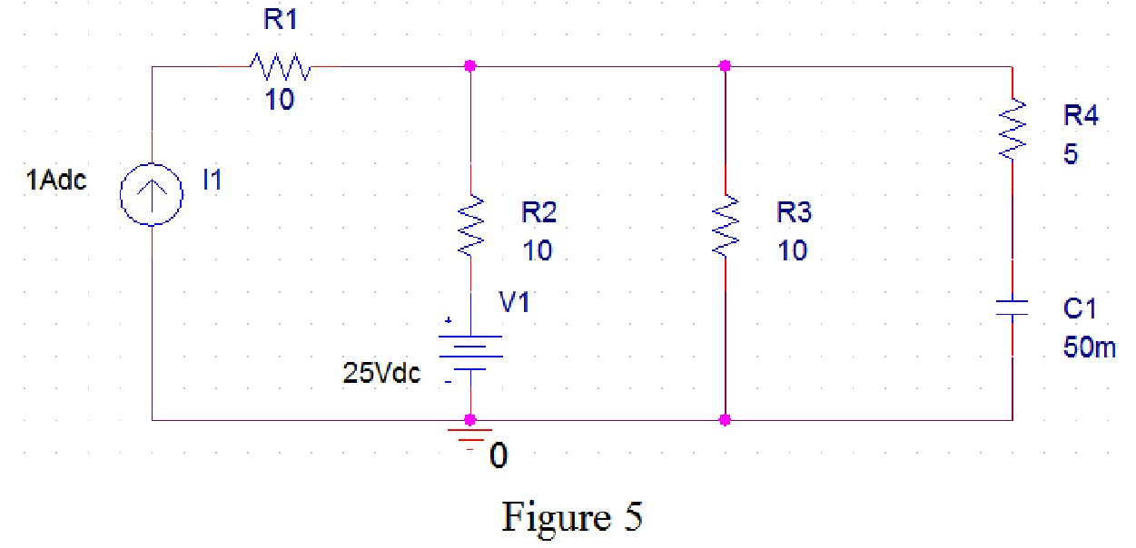
Draw the circuit diagram in PSpice as shown in Figure 5.
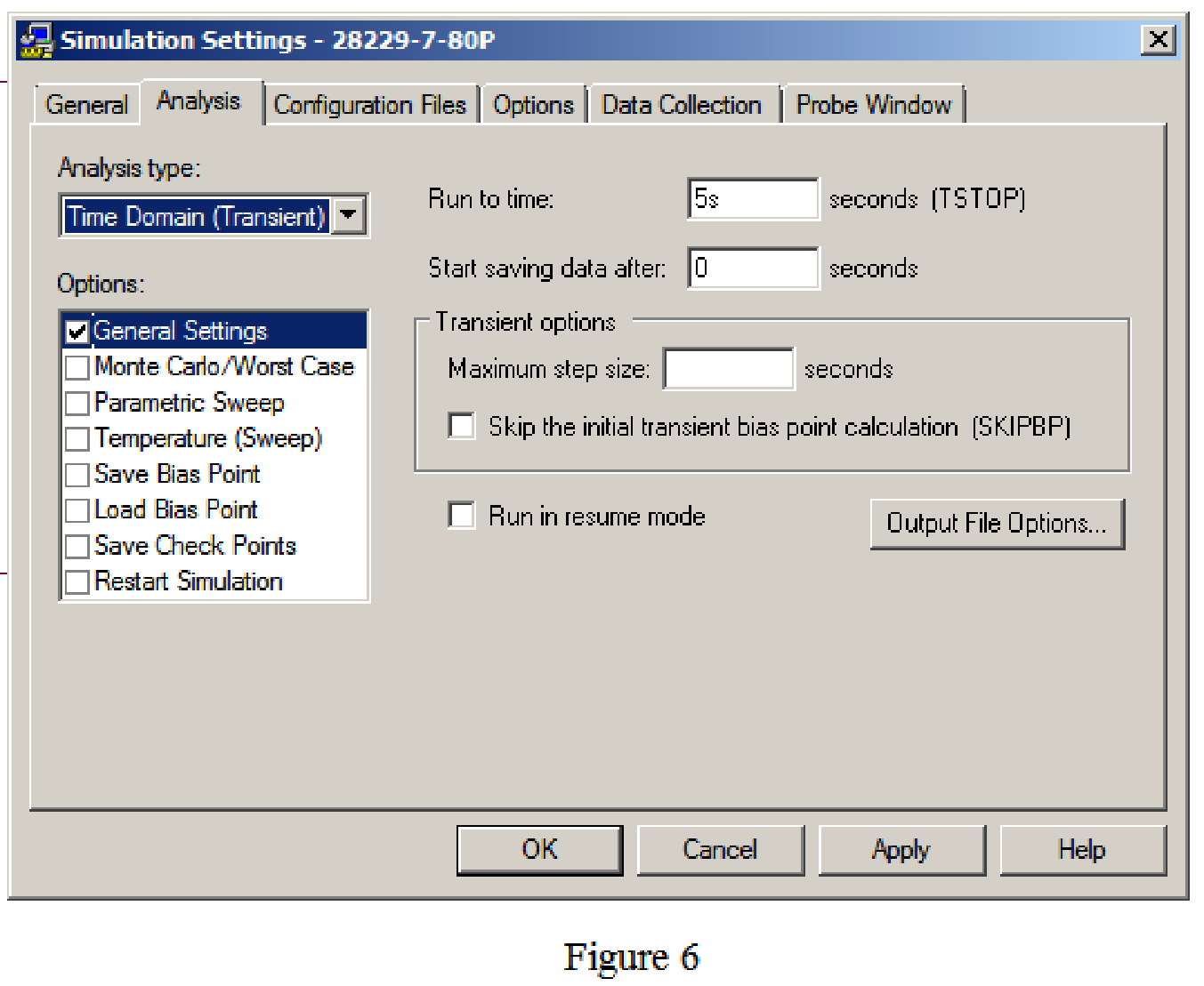
Save the circuit and provide the Simulation Settings as shown in Figure 6.
Now run the simulation and the results will be displayed as shown in Figure 7 by enabling “Enable Bias Voltage Display” icon.
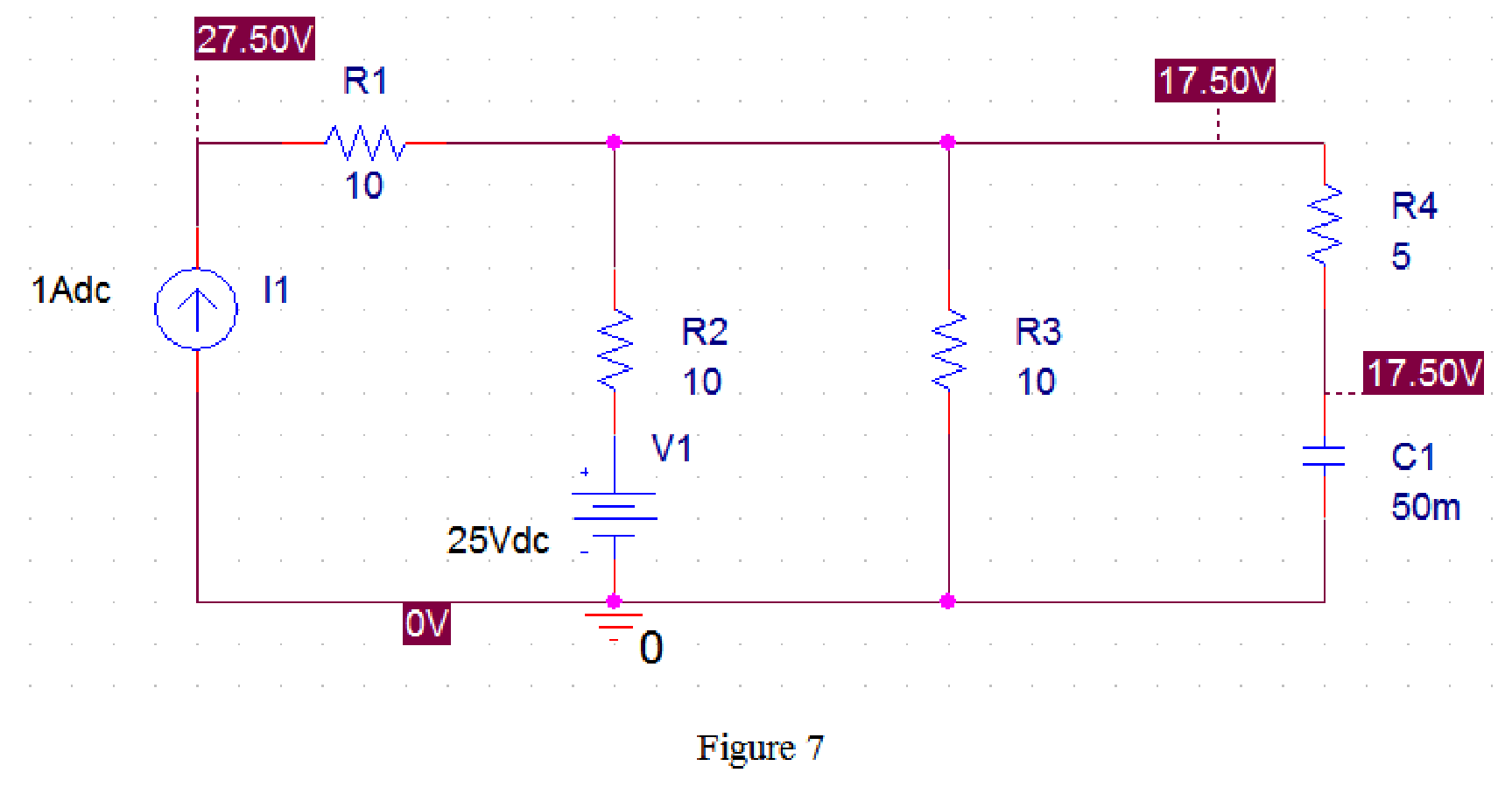
From Figure 7, the initial voltage across the capacitor is 17.5 V.
For
Draw the circuit diagram in PSpice as shown in Figure 8.
Now run the simulation and the results will be displayed as shown in Figure 8 by enabling “Enable Bias Voltage Display” icon.
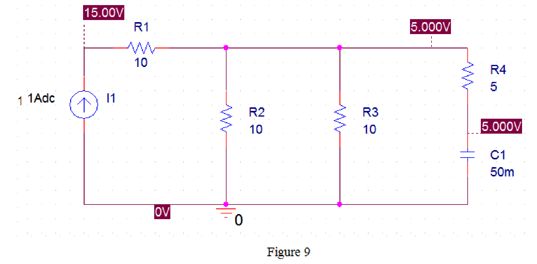
From Figure 9, the final voltage across the capacitor is 5 V.
Draw the circuit diagram in PSpice as shown in Figure 10.
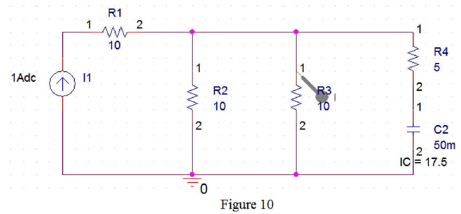
Now run the simulation and the results will be displayed as shown in Figure 11 by enabling “Enable Bias Voltage Display” icon and place the “Current Marker”
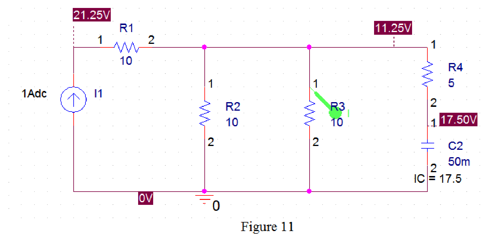
The SCHEMATIC1 dialog box is also opened with simulation result as shown in Figure 12.
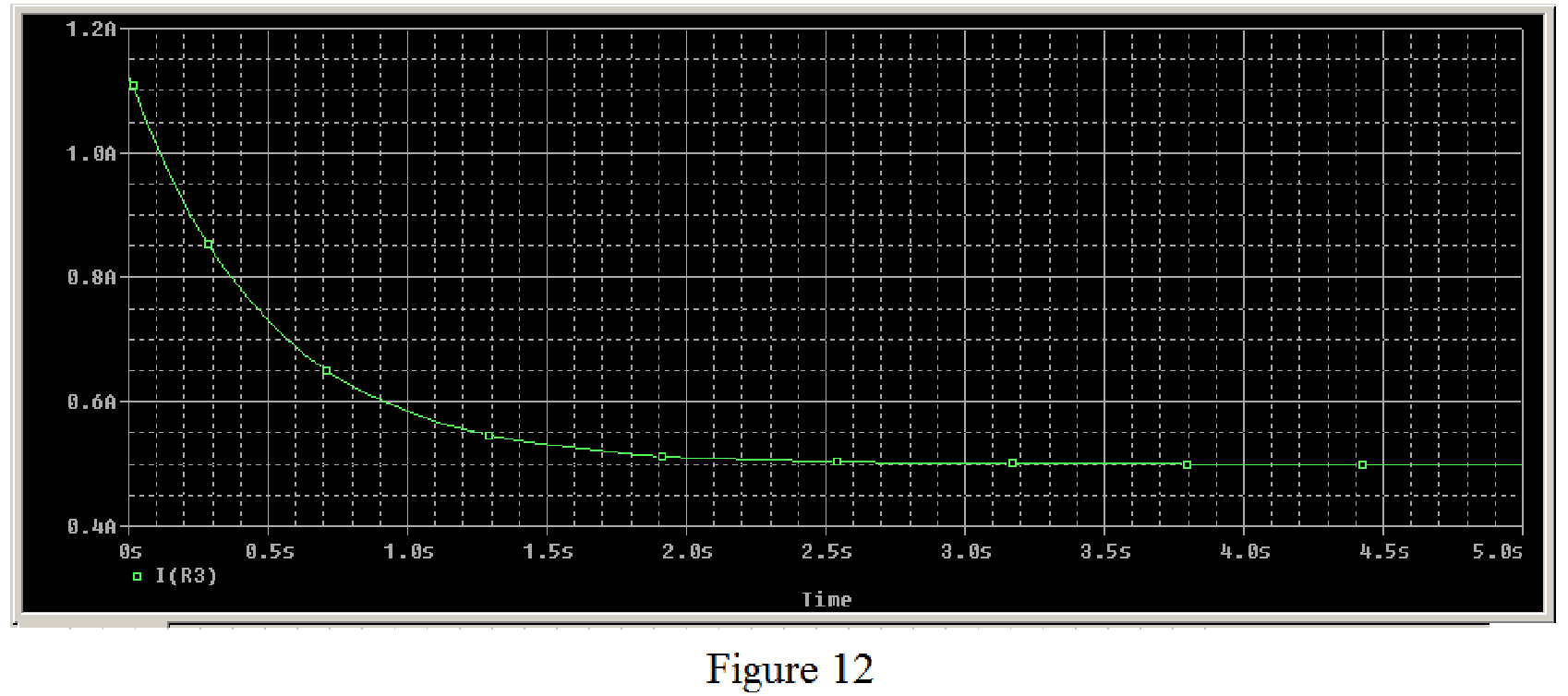
Therefore, the plot of current through the
Conclusion:
Thus, the current
Want to see more full solutions like this?
Chapter 7 Solutions
Fundamentals of Electric Circuits


- Please solve it by explaining the steps. I am trying to prepare for my exam tomorrow, so any tips and tricks to solve similar problems are highly appreciated. Plus, this is a past exam I am using to prepare.arrow_forwardPlease solve it by explaining the steps. I am trying to prepare for my exam tomorrow, so any tips and tricks to solve similar problems are highly appreciated. Plus, this is a past exam I am using to prepare.arrow_forwardPlease solve it by explaining the steps. I am trying to prepare for my exam tomorrow, so any tips and tricks to solve similar problems are highly appreciated. Plus, this is a past exam I am using to prepare.arrow_forward
- Please solve it by explaining the steps. I am trying to prepare for my exam tomorrow, so any tips and tricks to solve similar problems are highly appreciated. Plus, this is a past exam I am using to prepare.arrow_forwardPlease solve it by explaining the steps. I am trying to prepare for my exam tomorrow, so any tips and tricks to solve similar problems are highly appreciated. Plus, this is a past exam I am using to prepare.arrow_forwardPlease solve it by explaining the steps. I am trying to prepare for my exam tomorrow, so any tips and tricks to solve similar problems are highly appreciated. Plus, this is a past exam I am using to prepare.arrow_forward
- It is a past exam for practice, please explain what you do so I can be prepared for exam tomorrowarrow_forwardPlease solve it by explaining the steps. I am trying to prepare for my exam tomorrow, so any tips and tricks to solve similar problems are highly appreciated. Plus, this is a past exam I am using to prepare.arrow_forwardPlease solve it by explaining the steps. I am trying to prepare for my exam tomorrow, so any tips and tricks to solve similar problems are highly appreciated. Plus, this is a past exam I am using to prepare.arrow_forward
- Please solve it by explaining the steps. I am trying to prepare for my exam tomorrow, so any tips and tricks to solve similar problems are highly appreciated. Plus, this is a past exam I am using to prepare.arrow_forwardIf C is the circle |z|=4 evaluate ff(z)dz for each of the following functions using residue. Z (a)f(z) = z²-1 Z+1 1 (b)f(z) = = (c)f(z) = z²(z+2) z(z-2)³ z² 1 1 (d) f(z) = = (e) f(z) = (f) f(z) = (z²+3z+2)² z²+z+1 z(z²+6z+4)arrow_forward5. Answer the following questions. Take help from ChatGPT to answer these questions (if you need). Write the answers briefly using your own words with no more than two sentences, and check whether ChatGPT is giving you the appropriate answers in the context of our class. a) What is the Bode plot? What kind of input do we consider for the frequency-response- based method? b) What is the advantage of design using the frequency-response method? c) Define gain margin, phase margin, gain crossover frequency, and phase crossover frequency.arrow_forward
 Introductory Circuit Analysis (13th Edition)Electrical EngineeringISBN:9780133923605Author:Robert L. BoylestadPublisher:PEARSON
 Delmar's Standard Textbook Of ElectricityElectrical EngineeringISBN:9781337900348Author:Stephen L. HermanPublisher:Cengage Learning
 Programmable Logic ControllersElectrical EngineeringISBN:9780073373843Author:Frank D. PetruzellaPublisher:McGraw-Hill Education
 Fundamentals of Electric CircuitsElectrical EngineeringISBN:9780078028229Author:Charles K Alexander, Matthew SadikuPublisher:McGraw-Hill Education
 Electric Circuits. (11th Edition)Electrical EngineeringISBN:9780134746968Author:James W. Nilsson, Susan RiedelPublisher:PEARSON
 Engineering ElectromagneticsElectrical EngineeringISBN:9780078028151Author:Hayt, William H. (william Hart), Jr, BUCK, John A.Publisher:Mcgraw-hill Education,