
Fundamentals of Electric Circuits
6th Edition
ISBN: 9780078028229
Author: Charles K Alexander, Matthew Sadiku
Publisher: McGraw-Hill Education
expand_more
expand_more
format_list_bulleted
Concept explainers
Videos
Textbook Question
Chapter 7, Problem 81P
Repeat Prob. 7.65 using PSpice or MultiSim.
If the input pulse in Fig. 7.130(a) is applied to the circuit in Fig. 7.130(b), determine the response i(t).
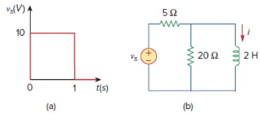
Figure 7.130
Expert Solution & Answer
Want to see the full answer?
Check out a sample textbook solution
Students have asked these similar questions
Sketch the output of the analogue computer shown below and find its closest
describing function [suppose any variable to find the DF]
+1
ew2
HI
e2
1.0 +21
LO
SJ
eo
SJ
ew
LO
1.0 +|e1|
HI
-1
ew1 ek(1 + e。)
|e1|
k =
1+|e1|
Figure V-5
Feedback Limiter Behavior
ROUNDED, DUE TO DIODE
NONLINEARITY
LIMIT VOLTAGE
409
DIODE CONDUCTS
First, write the output transaction, then draw the output wave, and then find the
Describing function. I need to solve the question step by step, with an explanation
of each step.
Sketch the output of the analogue computer shown below and find its closest
describing function [suppose any variable to find the DF]
SJ
ew2
ew₁
HI
|e2|
2
LO
1.0 +21
LO
-1
HI
Jel
1.0+|e1|
ROUNDED, DUE TO DODE
NONLINEARITY
LIMIT VOLTAGE
DIODE CONDUCTS
ew1e, -k(1+ e。)
k
=
|e1|
1+|e1|
Figure 1-5 Feedback Limiter Behavior
First, write the output transaction, then draw the output wave, and then find the
Describing function. I need to solve the question step by step, with an explanation
of each step.
Sketch the output of the analogue computer shown below and find its closest
describing function [suppose any variable to find the DF]
SJ
+1
HI
LO
e2
1.0 +21
ew2
eo
SJ
ew₁
LO
Jel
1.0 +|e1|
HI
-1
ew1 ek(1+eo)
k =
|e1|
1+|e1|
First, write the output transaction, then draw the output wave, and then find the
Describing function. I need to solve the question step by step, with an explanation
of each step.
Chapter 7 Solutions
Fundamentals of Electric Circuits
Ch. 7.2 - Refer to the circuit in Fig. 7.7. Let vC (0) = 60...Ch. 7.2 - If the switch in Fig. 7.10 opens at t = 0, find...Ch. 7.3 - Find i and vx in the circuit of Fig. 7.15. Let...Ch. 7.3 - For the circuit in Fig. 7.18, find i(t) for t 0....Ch. 7.3 - Determine i, io, and vo for all t in the circuit...Ch. 7.4 - Express the current pulse in Fig. 7.33 in terms of...Ch. 7.4 - Refer to Fig. 7.39. Express i(t) in terms of...Ch. 7.4 - If h t = 0, t0 4, 0t2 3t8, 2t6 0, t6 express h(t)...Ch. 7.4 - Practice Problem 7.9 Evaluate the following...Ch. 7.5 - Find v(t) for t 0 in the circuit of Fig. 7.44....
Ch. 7.5 - The switch in Fig. 7.47 is closed at t = 0. Find...Ch. 7.6 - The switch in Fig. 7.52 has been closed for a long...Ch. 7.6 - Switch S1 in Fig. 7.54 is closed at t = 0, and...Ch. 7.7 - For the op amp circuit in Fig. 7.56, find vo for t...Ch. 7.7 - Find v(t) and vo(t) in the op amp circuit of Fig....Ch. 7.7 - Obtain the step response vo(t) for the circuit in...Ch. 7.8 - For the circuit in Fig. 7.66, use Pspice to find...Ch. 7.8 - The switch in Fig. 7.71 was open for a long time...Ch. 7.9 - The RC circuit in Fig. 7.74 is designed to operate...Ch. 7.9 - The flash unit of a camera has a 2-mF capacitor...Ch. 7.9 - A relay has a resistance of 200 and an inductance...Ch. 7.9 - Prob. 22PPCh. 7 - An RC circuit has R = 2 and C = 4 F. The time...Ch. 7 - The time constant for an RL circuit with R = 2 ...Ch. 7 - A capacitor in an RC circuit with R = 2 and C = 4...Ch. 7 - An RL circuit has R = 2 and L = 4 H. The time...Ch. 7 - In the circuit of Fig. 7.79, the capacitor voltage...Ch. 7 - Figure 7.79 For Review Questions 7.5 and 7.6....Ch. 7 - For the circuit in Fig. 7.80, the inductor current...Ch. 7 - Figure 7.80 For Review Questions 7.7 and 7.8....Ch. 7 - If vs changes from 2 V to 4 V at t = 0, we may...Ch. 7 - The pulse in Fig. 7.116(a) can be expressed in...Ch. 7 - In the circuit shown in Fig. 7.81...Ch. 7 - Find the time constant for the RC circuit in Fig....Ch. 7 - Determine the time constant for the circuit in...Ch. 7 - The switch in Fig. 7.84 has been in position A for...Ch. 7 - Using Fig. 7.85, design a problem to help other...Ch. 7 - The switch in Fig. 7.86 has been closed for a long...Ch. 7 - Assuming that the switch in Fig. 7.87 has been in...Ch. 7 - For the circuit in Fig. 7.88, if...Ch. 7 - The switch in Fig. 7.89 opens at t = 0. Find vo...Ch. 7 - For the circuit in Fig. 7.90, find vo(t) for t 0....Ch. 7 - For the circuit in Fig. 7.91, find io for t 0....Ch. 7 - Using Fig. 7.92, design a problem to help other...Ch. 7 - In the circuit of Fig. 7.93,...Ch. 7 - Calculate the time constant of the circuit in Fig....Ch. 7 - Find the time constant for each of the circuits in...Ch. 7 - Determine the time constant for each of the...Ch. 7 - Consider the circuit of Fig. 7.97. Find vo(t) if...Ch. 7 - For the circuit in Fig. 7.98, determine vo(t) when...Ch. 7 - In the circuit of Fig. 7.99, find i(t) for t 0 if...Ch. 7 - For the circuit in Fig. 7.100, v = 90e50t V and i...Ch. 7 - In the circuit of Fig. 7.101, find the value of R...Ch. 7 - Find i(t) and v(t) for t 0 in the circuit of Fig....Ch. 7 - Consider the circuit in Fig. 7.103. Given that...Ch. 7 - Express the following signals in terms of...Ch. 7 - Design a problem to help other students better...Ch. 7 - Express the signals in Fig. 7.104 in terms of...Ch. 7 - Express v(t) in Fig. 7.105 in terms of step...Ch. 7 - Sketch the waveform represented by i(t) = [r(t) ...Ch. 7 - Sketch the following functions: (a) x(t) = 10etu(t...Ch. 7 - Prob. 30PCh. 7 - Evaluate the following integrals: (a)e4t2(t2)dt...Ch. 7 - Prob. 32PCh. 7 - The voltage across a 10-mH inductor is 45(t 2)mV....Ch. 7 - Evaluate the following derivatives: (a) ddtut1ut+1...Ch. 7 - Find the solution to the following differential...Ch. 7 - Solve for v in the following differential...Ch. 7 - A circuit is described by 4dvdt+v=10 (a) What is...Ch. 7 - A circuit is described by didt+3i=2ut Find i(t)...Ch. 7 - Calculate the capacitor voltage for t 0 and t 0...Ch. 7 - Find the capacitor voltage for t 0 and t 0 for...Ch. 7 - Using Fig. 7.108, design a problem to help other...Ch. 7 - (a) If the switch in Fig. 7.109 has been open for...Ch. 7 - Consider the circuit in Fig. 7.110. Find i(t) for...Ch. 7 - The switch in Fig. 7.111 has been in position a...Ch. 7 - Find vo in the circuit of Fig. 7.112 when vs =...Ch. 7 - Prob. 46PCh. 7 - Determine v(t) for t 0 in the circuit of Fig....Ch. 7 - Find v(t) and i(t) in the circuit of Fig. 7.115....Ch. 7 - If the waveform in Fig. 7.116(a) is applied to the...Ch. 7 - In the circuit of Fig. 7.117, find ix for t 0....Ch. 7 - Rather than applying the shortcut technique used...Ch. 7 - Using Fig. 7.118, design a problem to help other...Ch. 7 - Determine the inductor current i(t) for both t 0...Ch. 7 - Obtain the inductor current for both t 0 and t 0...Ch. 7 - Find v(t) for t 0 and t 0 in the circuit of Fig....Ch. 7 - Prob. 56PCh. 7 - Prob. 57PCh. 7 - Rework Prob. 7.17 if i(0) = 10 A and v(t) = 20u(t)...Ch. 7 - Determine the step response vo(t) to is = 6u(t) A...Ch. 7 - Find v(t) for t 0 in the circuit of Fig. 7.125 if...Ch. 7 - In the circuit in Fig. 7.126, is changes from 5 A...Ch. 7 - For the circuit in Fig. 7.127, calculate i(t) if...Ch. 7 - Obtain v(t) and i(t) in the circuit of Fig. 7.128....Ch. 7 - Determine the value of iL(t) and the total energy...Ch. 7 - If the input pulse in Fig. 7.130(a) is applied to...Ch. 7 - Using Fig. 7.131, design a problem to help other...Ch. 7 - If v(0) = 10 V, find vo(t) for t 0 in the op amp...Ch. 7 - Prob. 68PCh. 7 - For the op amp circuit in Fig. 7.134, find vo(t)...Ch. 7 - Determine vo for t 0 when vs = 20 mV in the op...Ch. 7 - For the op amp circuit in Fig. 7.136, suppose vs =...Ch. 7 - Find io in the op amp circuit in Fig. 7.137....Ch. 7 - For the op amp circuit of Fig. 7.138, let R1 = 10...Ch. 7 - Determine vo(t) for t 0 in the circuit of Fig....Ch. 7 - In the circuit of Fig. 7.140, find vo and io,...Ch. 7 - Repeat Prob. 7.49 using PSpice or MultiSim. If the...Ch. 7 - The switch in Fig. 7.141 opens at t = 0. Use...Ch. 7 - The switch in Fig. 7.142 moves from position a to...Ch. 7 - In the circuit of Fig. 7.143, determine io(t)....Ch. 7 - In the circuit of Fig. 7.144, find the value of io...Ch. 7 - Repeat Prob. 7.65 using PSpice or MultiSim. If the...Ch. 7 - In designing a signal-switching circuit, it was...Ch. 7 - Prob. 83PCh. 7 - A capacitor with a value of 10 mF has a leakage...Ch. 7 - A simple relaxation oscillator circuit is shown in...Ch. 7 - Figure 7.146 shows a circuit for setting the...Ch. 7 - A 120-V dc generator energizes a motor whose coil...Ch. 7 - The circuit in Fig. 7.148(a) can be designed as an...Ch. 7 - An RL circuit may be used as a differentiator if...Ch. 7 - An attenuator probe employed with oscilloscopes...Ch. 7 - The circuit in Fig. 7.150 is used by a biology...Ch. 7 - To move a spot of a cathode-ray tube across the...
Knowledge Booster


Learn more about
Need a deep-dive on the concept behind this application? Look no further. Learn more about this topic, electrical-engineering and related others by exploring similar questions and additional content below.Similar questions
- Can you help me find the result of an integral 0/2 a² X + a dxarrow_forwardQ1/Sketch the root locus for the system shown in Figure 1 and find the following: a. The exact point and gain where the locus crosses the jo-axis b. The breakaway point on the real axis c. The range of K within which the system is stable d. Angles of departure and arrival R(s) + K(s²-4s +20) C(s) (s+2)(s + 4)arrow_forwardExam2 Subject: (Numerical Analysis) Class: Third Date: 27/4/2025 Time: 60 minutes Q1. For what values of k does this system of equations has no solution? (use Gauss-Jordan eliminations) kx + y + z = 1 x+ky + z = 1 x+y+kz=1arrow_forward
- Consider the Difference equation of a causal Linear time-invariant (LTI) system given by: (y(n) - 1.5y(n - 1) + 0.5y(n = 2) = x(n) a) Implement the difference equation model of this system. b) Find the system transfer function H(z). c) For an input x(n) = 8(n), determine the output response y(n). d) Verify the initial value theorem y(0) with part (c).arrow_forwardQ5B. Find the type of the controller in the following figures and use real values to find the transfer function of three of them[ Hint Pi,Pd and Lead,lag are found so put the controller with its corresponding compensator]. R₁ R₂ Rz HE C2 RA HE R₁ R2 RA とarrow_forwardQ1// Sketch the root locus for the unity feedback system. Where G(s)=)= K S3+252 +25 and find the following a. Sketch the asymptotes b. The exact point and gain where the locus crosses the jo-axis c. The breakaway point on the real axis d. The range of K within which the system is stable e. Angles of departure and arrival.arrow_forward
- Determine X(w) for the given function shown in Figure (1) by applying the differentiation property of the Fourier Transform. Figure (1) -1 x(t)arrow_forwardCan you solve a question with a drawing Determine X(w) for the given function shown in Figure (1) by applying the differentiation property of the Fourier Transform. Figure (1) -1 x(t)arrow_forwardAn inductor has a current flow of 3 A when connected to a 240 V, 60 Hz power line. The inductor has a wire resistance of 15 Find the Q of the inductorarrow_forward
- صورة من s94850121arrow_forwardThe joint density function of two continuous random variables X and Yis: p(x, y) = {Keós (x + y) Find (i) the constant K 0 2 0arrow_forwardShow all the steps please, Solve for the current through R2 if E2 is replaced by a current source of 10mA using superposition theorem. R5=470Ω R2=1000Ω R6=820Ωarrow_forwardarrow_back_iosSEE MORE QUESTIONSarrow_forward_ios
Recommended textbooks for you
 Introductory Circuit Analysis (13th Edition)Electrical EngineeringISBN:9780133923605Author:Robert L. BoylestadPublisher:PEARSON
 Delmar's Standard Textbook Of ElectricityElectrical EngineeringISBN:9781337900348Author:Stephen L. HermanPublisher:Cengage Learning
 Programmable Logic ControllersElectrical EngineeringISBN:9780073373843Author:Frank D. PetruzellaPublisher:McGraw-Hill Education
 Fundamentals of Electric CircuitsElectrical EngineeringISBN:9780078028229Author:Charles K Alexander, Matthew SadikuPublisher:McGraw-Hill Education
 Electric Circuits. (11th Edition)Electrical EngineeringISBN:9780134746968Author:James W. Nilsson, Susan RiedelPublisher:PEARSON
 Engineering ElectromagneticsElectrical EngineeringISBN:9780078028151Author:Hayt, William H. (william Hart), Jr, BUCK, John A.Publisher:Mcgraw-hill Education,
Introductory Circuit Analysis (13th Edition)
Electrical Engineering
ISBN:9780133923605
Author:Robert L. Boylestad
Publisher:PEARSON
Delmar's Standard Textbook Of Electricity
Electrical Engineering
ISBN:9781337900348
Author:Stephen L. Herman
Publisher:Cengage Learning
Programmable Logic Controllers
Electrical Engineering
ISBN:9780073373843
Author:Frank D. Petruzella
Publisher:McGraw-Hill Education
Fundamentals of Electric Circuits
Electrical Engineering
ISBN:9780078028229
Author:Charles K Alexander, Matthew Sadiku
Publisher:McGraw-Hill Education
Electric Circuits. (11th Edition)
Electrical Engineering
ISBN:9780134746968
Author:James W. Nilsson, Susan Riedel
Publisher:PEARSON
Engineering Electromagnetics
Electrical Engineering
ISBN:9780078028151
Author:Hayt, William H. (william Hart), Jr, BUCK, John A.
Publisher:Mcgraw-hill Education,
ENA 9.2(1)(En)(Alex) Sinusoids & Phasors - Explanation with Example 9.1 ,9.2 & PP 9.2; Author: Electrical Engineering Academy;https://www.youtube.com/watch?v=vX_LLNl-ZpU;License: Standard YouTube License, CC-BY
Electrical Engineering: Ch 10 Alternating Voltages & Phasors (8 of 82) What is a Phasor?; Author: Michel van Biezen;https://www.youtube.com/watch?v=2I1tF3ixNg0;License: Standard Youtube License