
Engineering Mechanics: Statics
13th Edition
ISBN: 9780132915540
Author: Russell C. Hibbeler
Publisher: Prentice Hall
expand_more
expand_more
format_list_bulleted
Concept explainers
Videos
Textbook Question
Chapter 7.3, Problem 13FP
Draw the shear and moment diagrams for the beam.
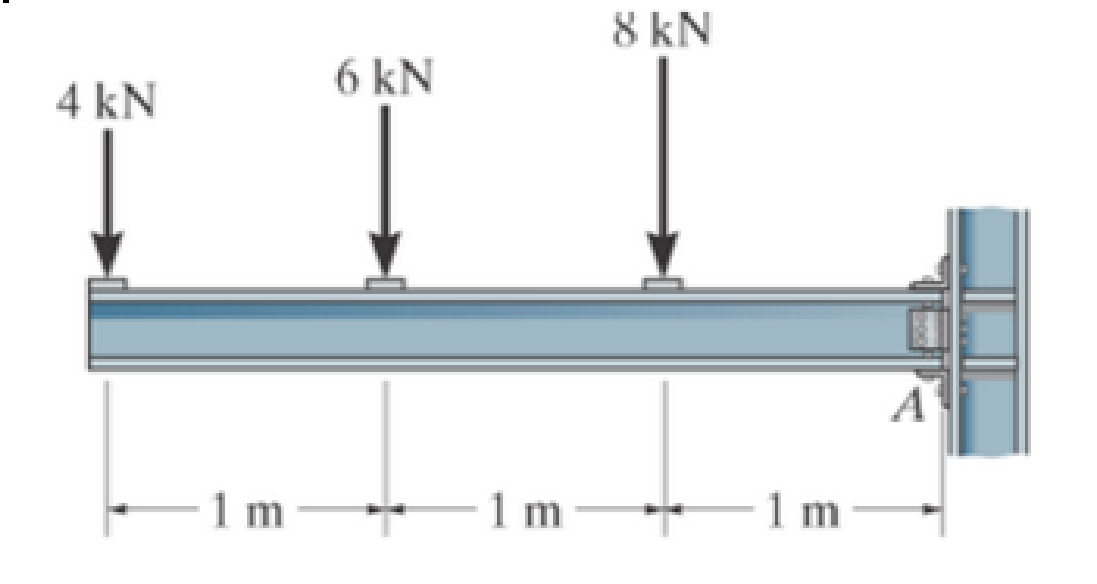
Prob. F7-13
Expert Solution & Answer

Learn your wayIncludes step-by-step video

schedule06:40
Students have asked these similar questions
A 3-in.-radius drum is rigidly attached to a 5-in.-radius drum as shown. One of the drums rolls without sliding on the surface shown, and a cord is wound around the other drum. Knowing that at the instant shown. point A has a velocity of 4.875 in./sin./s and an acceleration of 15.50 in./s2in./s2 , both directed to the right, determine the accelerations of points A, B, and C of the drums.
The cord is wound around the 3 inch radius drum. Point B is at the bottom of the 5 inch radius drum. Point A is at the bottom of the 3 inch radius drum. Point C is on the right edge of the 5 inch radius drum.
The accelerations of point B is______ in./s2 .
The accelerations of point A is ______ in./s2 ______ ⦨ °. at what angle/direction
The accelerations of point C is______ in./s2 ______ ⦪ °. at what angle/direction?
A total volume of mud is 1,000 bbls that has a mud weight of 9.1 ppg. Calculate the volumefractions of water, Bentonite, and the weight of Bentonite used. Density of powder Bentonite is 156 lbm/ft3
A 3-in.-radius drum is rigidly attached to a 5-in.-radius drum as shown. One of the drums rolls without sliding on the surface shown, and a cord is wound around the other drum. Knowing that at the instant shown. point A has a velocity of 4.875 in./sin./s and an acceleration of 15.50 in./s2in./s2 , both directed to the right, determine the accelerations of points A, B, and C of the drums.
The cord is wound around the 3 inch radius drum. Point B is at the bottom of the 5 inch radius drum. Point A is at the bottom of the 3 inch radius drum. Point C is on the right edge of the 5 inch radius drum.
The accelerations of point B is ______ in./s2
The accelerations of point A is ______ in./s2 _____⦨ °.
The accelerations of point C is _______ in./s2 ____ ⦪ °.
Chapter 7 Solutions
Engineering Mechanics: Statics
Ch. 7.1 - Determine the normal force, shear force, and...Ch. 7.1 - Determine the normal force, shear force, and...Ch. 7.1 - Determine the normal force, shear force, and...Ch. 7.1 - Determine the normal force, shear force, and...Ch. 7.1 - Determine the normal force, shear force, and...Ch. 7.1 - Assume A is pinned and B is a roller. Prob. F7-6Ch. 7.1 - Assume the support at B is a roller. Point C is...Ch. 7.1 - Determine the shear force and moment at points C...Ch. 7.1 - If the suspended load has a weight of 2 kN and a...Ch. 7.1 - Prob. 4P
Ch. 7.1 - Prob. 5PCh. 7.1 - Determine the distance a as a fraction of the...Ch. 7.1 - Prob. 7PCh. 7.1 - Prob. 8PCh. 7.1 - Take P = 8 kN. Prob. 7-9Ch. 7.1 - Determine the largest vertical load P the frame...Ch. 7.1 - The shaft is supported by a journal bearing at A...Ch. 7.1 - Determine the internal normal force, shear force,...Ch. 7.1 - Prob. 13PCh. 7.1 - Prob. 14PCh. 7.1 - Prob. 15PCh. 7.1 - Prob. 16PCh. 7.1 - Prob. 17PCh. 7.1 - Point E is just to the right of the 3-kip load....Ch. 7.1 - Prob. 19PCh. 7.1 - Determine the internal normal force, shear force,...Ch. 7.1 - Prob. 21PCh. 7.1 - Prob. 22PCh. 7.1 - Prob. 23PCh. 7.1 - Determine the internal normal force, shear force,...Ch. 7.1 - Prob. 25PCh. 7.1 - Determine the ratio of a/b for which the shear...Ch. 7.1 - Prob. 27PCh. 7.1 - Prob. 28PCh. 7.1 - Determine the normal force, shear force, and...Ch. 7.1 - Determine the normal force, shear force, and...Ch. 7.1 - Prob. 31PCh. 7.1 - Prob. 32PCh. 7.1 - Prob. 33PCh. 7.1 - Prob. 34PCh. 7.1 - Prob. 35PCh. 7.1 - Prob. 36PCh. 7.1 - Prob. 37PCh. 7.1 - Prob. 38PCh. 7.1 - Prob. 39PCh. 7.1 - Prob. 40PCh. 7.1 - Determine the x, y, z components of force and...Ch. 7.1 - z components of force and moment at point C in the...Ch. 7.1 - Prob. 43PCh. 7.1 - Prob. 44PCh. 7.2 - Determine the shear and moment as a function of x,...Ch. 7.2 - Determine the shear and moment as a function of x,...Ch. 7.2 - Determine the shear and moment as a function of x,...Ch. 7.2 - Determine the shear and moment as a function of x,...Ch. 7.2 - Determine the shear and moment as a function of x,...Ch. 7.2 - Determine the shear and moment as a function of x,...Ch. 7.2 - Prob. 45PCh. 7.2 - Draw the shear and moment diagrams for the beam...Ch. 7.2 - Draw the shear and moment diagrams for the beam...Ch. 7.2 - Draw the shear and moment diagrams of the beam (a)...Ch. 7.2 - If L = 9 m, the beam will fail when the maximum...Ch. 7.2 - Draw the shear and moment diagrams for the...Ch. 7.2 - Prob. 51PCh. 7.2 - Prob. 52PCh. 7.2 - Draw the shear and moment diagrams for the beam....Ch. 7.2 - Prob. 54PCh. 7.2 - Draw the shear and bending-moment diagrams for the...Ch. 7.2 - Prob. 56PCh. 7.2 - Draw the shear and bending-moment diagrams for...Ch. 7.2 - Draw the shear and moment diagrams for the...Ch. 7.2 - Prob. 59PCh. 7.2 - The shaft is supported by a smooth thrust bearing...Ch. 7.2 - Prob. 61PCh. 7.2 - Prob. 62PCh. 7.2 - Prob. 63PCh. 7.2 - Prob. 64PCh. 7.2 - Prob. 65PCh. 7.2 - Draw the shear and moment diagrams for the beam....Ch. 7.2 - Prob. 67PCh. 7.2 - Prob. 68PCh. 7.2 - Express the internal shear and moment components...Ch. 7.3 - Draw the shear and moment diagrams for the beam....Ch. 7.3 - Draw the shear and moment diagrams for the beam....Ch. 7.3 - Draw the shear and moment diagrams for the beam....Ch. 7.3 - Draw the shear and moment diagrams for the beam....Ch. 7.3 - Draw the shear and moment diagrams for the beam....Ch. 7.3 - Draw the shear and moment diagrams for the beam....Ch. 7.3 - Prob. 70PCh. 7.3 - Prob. 71PCh. 7.3 - Draw the shear and moment diagrams for the beam....Ch. 7.3 - Prob. 73PCh. 7.3 - Draw the shear and moment diagrams for the...Ch. 7.3 - Draw the shear and moment diagrams for the beam....Ch. 7.3 - Prob. 76PCh. 7.3 - Prob. 77PCh. 7.3 - Draw the shear and moment diagrams for the shaft....Ch. 7.3 - Draw the shear and moment diagrams for the beam....Ch. 7.3 - Prob. 80PCh. 7.3 - Prob. 81PCh. 7.3 - Prob. 82PCh. 7.3 - Prob. 83PCh. 7.3 - Prob. 84PCh. 7.3 - Prob. 85PCh. 7.3 - Prob. 86PCh. 7.3 - Prob. 87PCh. 7.3 - Prob. 88PCh. 7.3 - Prob. 89PCh. 7.3 - Prob. 90PCh. 7.3 - Prob. 91PCh. 7.3 - Prob. 92PCh. 7.3 - Prob. 93PCh. 7.4 - Prob. 94PCh. 7.4 - Prob. 95PCh. 7.4 - Determine the tension in each segment of the cable...Ch. 7.4 - Prob. 97PCh. 7.4 - Prob. 98PCh. 7.4 - Prob. 99PCh. 7.4 - If cylinder E has a mass of 20 kg and each cable...Ch. 7.4 - Prob. 101PCh. 7.4 - Prob. 102PCh. 7.4 - If yB = 1.5 ft. determine the largest weight of...Ch. 7.4 - The cable AB is subjected to a uniform loading of...Ch. 7.4 - Determine the maximum uniform loading w, measured...Ch. 7.4 - The cable is subjected to a uniform loading of w =...Ch. 7.4 - Prob. 107PCh. 7.4 - Prob. 108PCh. 7.4 - If the pipe has a mass per unit length of 1500...Ch. 7.4 - Prob. 110PCh. 7.4 - Prob. 111PCh. 7.4 - Prob. 112PCh. 7.4 - Prob. 113PCh. 7.4 - A telephone line (cable) stretches between two...Ch. 7.4 - Prob. 115PCh. 7.4 - Prob. 116PCh. 7.4 - Prob. 117PCh. 7.4 - A cable has a weight of 5 lb/ft. If it can span...Ch. 7.4 - Prob. 119PCh. 7.4 - The power transmission cable weighs 10 lb/fl. If...Ch. 7.4 - The power transmission cable weighs 10 lb/ft. If h...Ch. 7.4 - Prob. 122PCh. 7.4 - Prob. 123PCh. 7.4 - The man picks up the 52-ft chain and holds it just...Ch. 7.4 - Determine the internal normal force, shear force,...Ch. 7.4 - Draw the shear and moment diagrams for the beam....Ch. 7.4 - Prob. 127RPCh. 7.4 - Prob. 128RPCh. 7.4 - Prob. 129RPCh. 7.4 - Prob. 130RPCh. 7.4 - Prob. 131RPCh. 7.4 - Prob. 132RPCh. 7.4 - Draw the shear and moment diagrams for the beam....Ch. 7.4 - Determine the normal force, shear force, and...Ch. 7.4 - Draw the shear and moment diagrams for the beam....Ch. 7.4 - Prob. 137RPCh. 7.4 - Prob. 138RPCh. 7.4 - Prob. 139RP
Additional Engineering Textbook Solutions
Find more solutions based on key concepts
(Keyword new) Whats the purpose of keyword new? Explain what happens when you use it.
Java How to Program, Early Objects (11th Edition) (Deitel: How to Program)
17–1C A high-speed aircraft is cruising in still air. How does the temperature of air at the nose of the aircra...
Thermodynamics: An Engineering Approach
What parameters do you need to specify in order to calculate MRR in milling?
Degarmo's Materials And Processes In Manufacturing
The ________ object is assumed to exist and it is not necessary to include it as an object when referring to it...
Web Development and Design Foundations with HTML5 (8th Edition)
Pig Latin Design a program that reads a sentence as input and converts each word to Pig Latin. In one version o...
Starting Out with Programming Logic and Design (5th Edition) (What's New in Computer Science)
Assume this code is using the IntBinarySearcher class presented in this chapter: Int[] numbers = {8, 0, 9, 4, 3...
Starting Out with Java: From Control Structures through Data Structures (4th Edition) (What's New in Computer Science)
Knowledge Booster


Learn more about
Need a deep-dive on the concept behind this application? Look no further. Learn more about this topic, mechanical-engineering and related others by exploring similar questions and additional content below.Similar questions
- The average heat transfer coefficent for airflow over an odd shaped body is to be determined by mass transfer measurements and using the Chilton-Colburn analogy btwn heat and mass transfer. The experiemnt is conducted by blowing dry air at 1 atm at a free-stream velocity of 2 m/s over a body covered with a layer of naphthalene. The surface area of the body is .75 m^2, and it is observed that 100 g of maphthalene has sublimated in 45 min. During the experiemnt, both the body and the air were kep at 25oC, at which the vapor pressure and mass diffusivity of naphthalene are 11 Pa and Dab=0.61*10^-5 m^2/s respectively. Determine the heat transfer coefficent under the same flow conditions over the same geometry.arrow_forwardAuto Controls Design a PID controller for thefollowing system so that the modified system satisfies the followingspecifications : 1. settling time ,ts = 1.96 s and % Overshoot Mp = 70.7 % Assume a non-dominant pole at s = -15 to solve the problem The plot the compensated andThen plot the uncompensated system in MATLAB. what can you see from the plot ? what is your observation ?arrow_forwardAuto Controls The figure is a schematic diagram of an aircraft elevator control system. The input to the systemin the deflection angle of the control lever , and the output is the elevator angle phi.show that for each angle theta of the control lever ,there is a corresponding elevator angle phi. Then find Y(s)/theta(s) and simplify the resulting transfer function . Also note from the diagram that y and phi is relatedarrow_forward
- Fresh water is planned to be pumped in a certain pipe at constant pumping rate of 6.5 gpm. If water density and viscosity are 8.34 ppg and 1.0 cp, what is the minimum pipe inside diameter that make the fluid flow behave as turbulent flow?arrow_forwardUSE MATLAB ONLY provide typed code Turbomachienery . GIven: vx = 185 m/s, flow angle = 60 degrees, R = 0.5, U = 150 m/s, b2 = -a3, a2 = -b3 Find: velocity triangle , a. magnitude of abs vel leaving rotor (m/s) b. flow absolute angles (a1, a2, a3) 3. flow rel angles (b2, b3) d. specific work done e. use code to draw vel. diagram Use this code for plot % plots Velocity Tri. in Ch4 function plotveltri(al1,al2,al3,b2,b3) S1L = [0 1]; V1x = [0 0]; V1s = [0 1*tand(al3)]; S2L = [2 3]; V2x = [0 0]; V2s = [0 1*tand(al2)]; W2s = [0 1*tand(b2)]; U2x = [3 3]; U2y = [1*tand(b2) 1*tand(al2)]; S3L = [4 5]; V3x = [0 0]; V3r = [0 1*tand(al3)]; W3r = [0 1*tand(b3)]; U3x = [5 5]; U3y = [1*tand(b3) 1*tand(al3)]; plot(S1L,V1x,'k',S1L,V1s,'r',... S2L,V2x,'k',S2L,V2s,'r',S2L,W2s,'b',U2x,U2y,'g',... S3L,V3x,'k',S3L,V3r,'r',S3L,W3r,'b',U3x,U3y,'g',...... 'LineWidth',2,'MarkerSize',10),... axis([-1 6 -4 4]), ... title('Velocity Triangle'), ... xlabel('x'),ylarrow_forwardConsider a 12 cm internal diameter, 14 m long circular duct whose interior surface is wet. The duct is to be dried by forcing dry air at 1 atm and 15oC throught it at an average velocity of 3m/s. The duct passes through a chilled roo, and it remains at an average temp of 15oC at all time. Determine the mass transfer coeeficient in the duct.arrow_forward
- Consider a 5m by 5m wet concret patio with an average water film thickness of .2mm. Now wind at 50 km/h is blowing over the surface. If the air is at 1 atm, 15oC and 35 percent relative humidity, determine how long it will take for the patio to completely dry.arrow_forwardA double thread worm gear has a pitch of 1 1/8 and a pitch diameter of 3 in. It has a coefficient of friction of 0.20 and normal angle (pressure angle) of 14.5o. The worm is supplied by 12 hp at 1200 rpm motor. Find the tangential force on the gear. The worm is left hand threads.arrow_forwardA double thread worm gear has a pitch of 1 1/8 and a pitch diameter of 3 in. It has a coefficient of friction of 0.20 and normal angle (pressure angle) of 14.5o. The worm is supplied by 12 hp at 1200 rpm motor. Find the tangential force on the gear. The worm is left hand threads.arrow_forward
- A 2 mm thick, 5L vessel made of nickel is used ot store hydrogen gas at 358 K and 300 kPa. If the total inner surface area of the vessel is 1600 cm^2, determine the rate of gas loss from the nickel vessel via mas diffusion. Also, determine the fraction of the hydrogen lost by mass diffusion after one year of storage.arrow_forward< 7:19 The 1st homework 6. Multiple Choice a)唧筒机构 5G31 Which of followings can be th e kinematic diagram of this mechanism? A B Darrow_forward2:54 The 1st homework . 5G 27 b)回转柱塞泵机构 Which of followings can be the kinematic diagram of this mechanis m? A B D Carrow_forward
arrow_back_ios
SEE MORE QUESTIONS
arrow_forward_ios
Recommended textbooks for you
 Elements Of ElectromagneticsMechanical EngineeringISBN:9780190698614Author:Sadiku, Matthew N. O.Publisher:Oxford University Press
 Mechanics of Materials (10th Edition)Mechanical EngineeringISBN:9780134319650Author:Russell C. HibbelerPublisher:PEARSON
 Thermodynamics: An Engineering ApproachMechanical EngineeringISBN:9781259822674Author:Yunus A. Cengel Dr., Michael A. BolesPublisher:McGraw-Hill Education
 Control Systems EngineeringMechanical EngineeringISBN:9781118170519Author:Norman S. NisePublisher:WILEY
 Mechanics of Materials (MindTap Course List)Mechanical EngineeringISBN:9781337093347Author:Barry J. Goodno, James M. GerePublisher:Cengage Learning
 Engineering Mechanics: StaticsMechanical EngineeringISBN:9781118807330Author:James L. Meriam, L. G. Kraige, J. N. BoltonPublisher:WILEY
Elements Of Electromagnetics
Mechanical Engineering
ISBN:9780190698614
Author:Sadiku, Matthew N. O.
Publisher:Oxford University Press
Mechanics of Materials (10th Edition)
Mechanical Engineering
ISBN:9780134319650
Author:Russell C. Hibbeler
Publisher:PEARSON
Thermodynamics: An Engineering Approach
Mechanical Engineering
ISBN:9781259822674
Author:Yunus A. Cengel Dr., Michael A. Boles
Publisher:McGraw-Hill Education
Control Systems Engineering
Mechanical Engineering
ISBN:9781118170519
Author:Norman S. Nise
Publisher:WILEY
Mechanics of Materials (MindTap Course List)
Mechanical Engineering
ISBN:9781337093347
Author:Barry J. Goodno, James M. Gere
Publisher:Cengage Learning
Engineering Mechanics: Statics
Mechanical Engineering
ISBN:9781118807330
Author:James L. Meriam, L. G. Kraige, J. N. Bolton
Publisher:WILEY
Understanding Shear Force and Bending Moment Diagrams; Author: The Efficient Engineer;https://www.youtube.com/watch?v=C-FEVzI8oe8;License: Standard YouTube License, CC-BY
Bending Stress; Author: moodlemech;https://www.youtube.com/watch?v=9QIqewkE6xM;License: Standard Youtube License