
Engineering Mechanics: Statics
13th Edition
ISBN: 9780132915540
Author: Russell C. Hibbeler
Publisher: Prentice Hall
expand_more
expand_more
format_list_bulleted
Concept explainers
Videos
Textbook Question
Chapter 7.1, Problem 2P
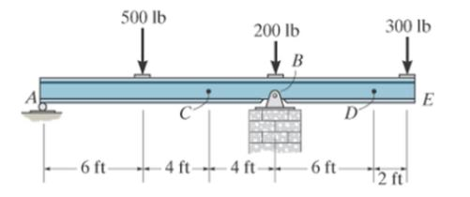
Determine the shear force and moment at points C and D.
Prob. 7-1
Expert Solution & Answer

Learn your wayIncludes step-by-step video

schedule09:43
Students have asked these similar questions
hand-written solutions only please!
hand-written solutions only please!
hand-written solutions only, please.
Chapter 7 Solutions
Engineering Mechanics: Statics
Ch. 7.1 - Determine the normal force, shear force, and...Ch. 7.1 - Determine the normal force, shear force, and...Ch. 7.1 - Determine the normal force, shear force, and...Ch. 7.1 - Determine the normal force, shear force, and...Ch. 7.1 - Determine the normal force, shear force, and...Ch. 7.1 - Assume A is pinned and B is a roller. Prob. F7-6Ch. 7.1 - Assume the support at B is a roller. Point C is...Ch. 7.1 - Determine the shear force and moment at points C...Ch. 7.1 - If the suspended load has a weight of 2 kN and a...Ch. 7.1 - Prob. 4P
Ch. 7.1 - Prob. 5PCh. 7.1 - Determine the distance a as a fraction of the...Ch. 7.1 - Prob. 7PCh. 7.1 - Prob. 8PCh. 7.1 - Take P = 8 kN. Prob. 7-9Ch. 7.1 - Determine the largest vertical load P the frame...Ch. 7.1 - The shaft is supported by a journal bearing at A...Ch. 7.1 - Determine the internal normal force, shear force,...Ch. 7.1 - Prob. 13PCh. 7.1 - Prob. 14PCh. 7.1 - Prob. 15PCh. 7.1 - Prob. 16PCh. 7.1 - Prob. 17PCh. 7.1 - Point E is just to the right of the 3-kip load....Ch. 7.1 - Prob. 19PCh. 7.1 - Determine the internal normal force, shear force,...Ch. 7.1 - Prob. 21PCh. 7.1 - Prob. 22PCh. 7.1 - Prob. 23PCh. 7.1 - Determine the internal normal force, shear force,...Ch. 7.1 - Prob. 25PCh. 7.1 - Determine the ratio of a/b for which the shear...Ch. 7.1 - Prob. 27PCh. 7.1 - Prob. 28PCh. 7.1 - Determine the normal force, shear force, and...Ch. 7.1 - Determine the normal force, shear force, and...Ch. 7.1 - Prob. 31PCh. 7.1 - Prob. 32PCh. 7.1 - Prob. 33PCh. 7.1 - Prob. 34PCh. 7.1 - Prob. 35PCh. 7.1 - Prob. 36PCh. 7.1 - Prob. 37PCh. 7.1 - Prob. 38PCh. 7.1 - Prob. 39PCh. 7.1 - Prob. 40PCh. 7.1 - Determine the x, y, z components of force and...Ch. 7.1 - z components of force and moment at point C in the...Ch. 7.1 - Prob. 43PCh. 7.1 - Prob. 44PCh. 7.2 - Determine the shear and moment as a function of x,...Ch. 7.2 - Determine the shear and moment as a function of x,...Ch. 7.2 - Determine the shear and moment as a function of x,...Ch. 7.2 - Determine the shear and moment as a function of x,...Ch. 7.2 - Determine the shear and moment as a function of x,...Ch. 7.2 - Determine the shear and moment as a function of x,...Ch. 7.2 - Prob. 45PCh. 7.2 - Draw the shear and moment diagrams for the beam...Ch. 7.2 - Draw the shear and moment diagrams for the beam...Ch. 7.2 - Draw the shear and moment diagrams of the beam (a)...Ch. 7.2 - If L = 9 m, the beam will fail when the maximum...Ch. 7.2 - Draw the shear and moment diagrams for the...Ch. 7.2 - Prob. 51PCh. 7.2 - Prob. 52PCh. 7.2 - Draw the shear and moment diagrams for the beam....Ch. 7.2 - Prob. 54PCh. 7.2 - Draw the shear and bending-moment diagrams for the...Ch. 7.2 - Prob. 56PCh. 7.2 - Draw the shear and bending-moment diagrams for...Ch. 7.2 - Draw the shear and moment diagrams for the...Ch. 7.2 - Prob. 59PCh. 7.2 - The shaft is supported by a smooth thrust bearing...Ch. 7.2 - Prob. 61PCh. 7.2 - Prob. 62PCh. 7.2 - Prob. 63PCh. 7.2 - Prob. 64PCh. 7.2 - Prob. 65PCh. 7.2 - Draw the shear and moment diagrams for the beam....Ch. 7.2 - Prob. 67PCh. 7.2 - Prob. 68PCh. 7.2 - Express the internal shear and moment components...Ch. 7.3 - Draw the shear and moment diagrams for the beam....Ch. 7.3 - Draw the shear and moment diagrams for the beam....Ch. 7.3 - Draw the shear and moment diagrams for the beam....Ch. 7.3 - Draw the shear and moment diagrams for the beam....Ch. 7.3 - Draw the shear and moment diagrams for the beam....Ch. 7.3 - Draw the shear and moment diagrams for the beam....Ch. 7.3 - Prob. 70PCh. 7.3 - Prob. 71PCh. 7.3 - Draw the shear and moment diagrams for the beam....Ch. 7.3 - Prob. 73PCh. 7.3 - Draw the shear and moment diagrams for the...Ch. 7.3 - Draw the shear and moment diagrams for the beam....Ch. 7.3 - Prob. 76PCh. 7.3 - Prob. 77PCh. 7.3 - Draw the shear and moment diagrams for the shaft....Ch. 7.3 - Draw the shear and moment diagrams for the beam....Ch. 7.3 - Prob. 80PCh. 7.3 - Prob. 81PCh. 7.3 - Prob. 82PCh. 7.3 - Prob. 83PCh. 7.3 - Prob. 84PCh. 7.3 - Prob. 85PCh. 7.3 - Prob. 86PCh. 7.3 - Prob. 87PCh. 7.3 - Prob. 88PCh. 7.3 - Prob. 89PCh. 7.3 - Prob. 90PCh. 7.3 - Prob. 91PCh. 7.3 - Prob. 92PCh. 7.3 - Prob. 93PCh. 7.4 - Prob. 94PCh. 7.4 - Prob. 95PCh. 7.4 - Determine the tension in each segment of the cable...Ch. 7.4 - Prob. 97PCh. 7.4 - Prob. 98PCh. 7.4 - Prob. 99PCh. 7.4 - If cylinder E has a mass of 20 kg and each cable...Ch. 7.4 - Prob. 101PCh. 7.4 - Prob. 102PCh. 7.4 - If yB = 1.5 ft. determine the largest weight of...Ch. 7.4 - The cable AB is subjected to a uniform loading of...Ch. 7.4 - Determine the maximum uniform loading w, measured...Ch. 7.4 - The cable is subjected to a uniform loading of w =...Ch. 7.4 - Prob. 107PCh. 7.4 - Prob. 108PCh. 7.4 - If the pipe has a mass per unit length of 1500...Ch. 7.4 - Prob. 110PCh. 7.4 - Prob. 111PCh. 7.4 - Prob. 112PCh. 7.4 - Prob. 113PCh. 7.4 - A telephone line (cable) stretches between two...Ch. 7.4 - Prob. 115PCh. 7.4 - Prob. 116PCh. 7.4 - Prob. 117PCh. 7.4 - A cable has a weight of 5 lb/ft. If it can span...Ch. 7.4 - Prob. 119PCh. 7.4 - The power transmission cable weighs 10 lb/fl. If...Ch. 7.4 - The power transmission cable weighs 10 lb/ft. If h...Ch. 7.4 - Prob. 122PCh. 7.4 - Prob. 123PCh. 7.4 - The man picks up the 52-ft chain and holds it just...Ch. 7.4 - Determine the internal normal force, shear force,...Ch. 7.4 - Draw the shear and moment diagrams for the beam....Ch. 7.4 - Prob. 127RPCh. 7.4 - Prob. 128RPCh. 7.4 - Prob. 129RPCh. 7.4 - Prob. 130RPCh. 7.4 - Prob. 131RPCh. 7.4 - Prob. 132RPCh. 7.4 - Draw the shear and moment diagrams for the beam....Ch. 7.4 - Determine the normal force, shear force, and...Ch. 7.4 - Draw the shear and moment diagrams for the beam....Ch. 7.4 - Prob. 137RPCh. 7.4 - Prob. 138RPCh. 7.4 - Prob. 139RP
Additional Engineering Textbook Solutions
Find more solutions based on key concepts
(Asterisked problems are associated with optional sections.) 20. Suppose you were given two stacks. If you were...
Computer Science: An Overview (13th Edition) (What's New in Computer Science)
Suppose that we add the following method to the class SalesReporter in Listing 7.4 so that a program using this...
Java: An Introduction to Problem Solving and Programming (8th Edition)
Person and Customer Classes Design a class named Person with fields for holding a persons name, address, and te...
Starting Out with Java: From Control Structures through Data Structures (4th Edition) (What's New in Computer Science)
In the following exercises, write a program to carry out the task. The program should use variables for each of...
Introduction To Programming Using Visual Basic (11th Edition)
For the circuit shown, use the node-voltage method to find v1, v2, and i1.
How much power is delivered to the c...
Electric Circuits. (11th Edition)
Thetakes the .class files containing the programs bytecodes and transfers them to primary memory.
Java How to Program, Early Objects (11th Edition) (Deitel: How to Program)
Knowledge Booster


Learn more about
Need a deep-dive on the concept behind this application? Look no further. Learn more about this topic, mechanical-engineering and related others by exploring similar questions and additional content below.Similar questions
- hand-written solutions only please!arrow_forwardA prototype automobile is designed to travel at 65 km/hr. A model of this design is tested in a wind tunnel with identical standard sea- level air properties at a 1:5 scale. The measured model drag is 529 N, enforcing dynamic similarity. Determine (a) the drag force on the prototype and (b) the power required to overcome this drag. See the equation Vm m = D V Dm (a) Dp = i (b) Pp = i N hparrow_forwardA new blimp will move at 6 m/s in 20°C air, and we want to predict the drag force. Using a 1: 14-scale model in water at 20°C and measuring a 2500-N drag force on the model, determine (a) the required water velocity, (b) the drag on the prototype blimp and, (c) the power that will be required to propel it through the air. (a) Vm = i (b) Dp = i (c) Pp = i m/s N Warrow_forward
- Drag measurements were taken for a sphere, with a diameter of 5 cm, moving at 3.7 m/s in water at 20°C. The resulting drag on the sphere was 10 N. For a balloon with 1-m diameter rising in air with standard temperature and pressure, determine (a) the velocity if Reynolds number similarity is enforced and (b) the drag force if the drag coefficient in the equation below is the dependent pi term. li ε pVI D 1 = CD = Q μ (a) Vp = i (b) Dp = i m/s Narrow_forwardCalculate the forces in all members of the truss shown using either the method of joints or the method of sectionsarrow_forward20-4-2025 Exam-2-Tribology Q1: What are the assumptions of hydrodynamic lubrication theory: Q2: Explain with sketch the cycle or process of engine lubrication system-pressurized lubrication system Q3: A short bearing is designed to operate with an eccentricity ratio = 0. 7. The journal diameter is 60 mm, and its speed is 1300 r.p.m. The journal is supported by a short hydrodynamic bearing of length L/D = 0. 5, and clearance ratio C/R = 103. The radial load on the bearing is 9800 N. a. Find the Sommerfeld number. b. Find the minimum viscosity of the lubricant for operating at ε = 0.7 c. Select a lubricant if the average bearing operating temperature is 70°c Q4: Two parallel circular disks of 100 mm diameter have a clearance of Imm between them. Under load, the downward velocity of the upper disk is 2 m/s. At the same time, the lower disk is stationary. The clearance is full of SAE 40 oil at a temperature of 60°c. a. Find the load on the upper disk that results in the instantaneous…arrow_forward
- Tribobolgy 15/2022 Monthly Exam. Automobile Eng. Dert 2nd Semster/3rd class Max. Mark: 100% 7. Viscosity of multi-grade oils (a) Reduces with temperature (c) is less sensitive to temperature (b) Increases with temperature (d) None of the above 8. In a hydrodynamic journal bearing if eccentricity ratio = 1, it means (a) Journal/shaft is subjected to no load and the rotational speed is very high. (b) Journal is subjected to no load and the rotational speed is moderate (c) Journal is subjected to very light load and the rotational speed is very high. (d) Journal is subjected to very high load and the rotational speed is negligible. Q4/ The journal speed of a 100mm diameter journal is 2500 rpm. The journal is supported by a short hydrodynamic bearing of length L=0.6D, eccentricity ratio = 0.75 and a clearance ratio C/R=0.001. The radial load on the bearing is 10 kN. The lubricant is SAE 30, and the operating temperature of the lubricant in the bearing is 700C. 1- Assume…arrow_forward1 of 2 Monthly Exam. Automobile Eng. Dert 2nd Semster/3rd class Max. Mark: 100% Q1/A/ Compare between the long and short journal bearings B/ With the help of Stribeck's curve, discuss different regimes of lubrication. C/ Explain the importance of Tribology in the design of different machine elements Q2 /A/ According to the SAE viscosity grading system all engine oils are divided into two classes: monograde and multi-grade. Compare between them? B/What are the differences between grease and Synthetic oils C/ Explain the effect of eccentricity ratio & with respect to hydrodynamic journal bearing. Q3/A/ What are the major factors which affect the selection of lubricants? B/What are the criteria to classify sliding bearings? C/ Answer of the following: 1. According to the SAE viscosity classification, the oil (SAE 40) is lower viscosity than the oil (SAE 20) at the same temperature. (True or False) 2. For a slow speed-highly loaded bearing, used oils of high viscosity; while for high-speed…arrow_forwardThe uniform rods have a mass per unit length of 10kg/m . (Figure 1)If the dashpot has a damping coefficient of c=50N⋅s/m , and the spring has a stiffness of k=600N/m , show that the system is underdamped, and then find the pendulum's period of oscillation.arrow_forward
- 10-50. The principal plane stresses and associated strains in a plane at a point are σ₁ = 30 ksi, σ₂ = -10 ksi, e₁ = 1.14(10-3), €2=-0.655(103). Determine the modulus of elasticity and Poisson's ratio. emps to plum... Wednesday FI a וח 2 Q Search 48 F5 - F6 4+ F7 FB F9 FIO FII F12 & * S 6 7 8 9 ㅁ F2 # *F3 3 $ 4 F4 % W E R T Y ப S ALT D F G H X C V B N J Σ H L ว { P [ ] ALT " DELETE BACKSPACE NUM LOCK T 7 HOME ENTER 4 PAUSE SHIFT CTRL Earrow_forward10−9. The state of strain at the point has components of ϵx = −100(10−6), ϵy = −200(10−6), and γxy=100(10−6). Use the strain transformation equations to determine (a) the in-plane principal strains and (b) the maximum in-plane shear strain and average normal strain. In each case specify the orientation of the element and show how the strains deform the element within the x−y plane.arrow_forwardThe strain gage is placed on the surface of the steel boiler as shown. If it is 0.5 in. long, determine the pressure in the boiler when the gage elongates 0.2(10−3) in. The boiler has a thickness of 0.5 in. and inner diameter of 60 in. Also, determine the maximum x, y in-plane shear strain in the material. Take Est=29(103)ksi, vst=0.3.arrow_forward
arrow_back_ios
SEE MORE QUESTIONS
arrow_forward_ios
Recommended textbooks for you
 Elements Of ElectromagneticsMechanical EngineeringISBN:9780190698614Author:Sadiku, Matthew N. O.Publisher:Oxford University Press
 Mechanics of Materials (10th Edition)Mechanical EngineeringISBN:9780134319650Author:Russell C. HibbelerPublisher:PEARSON
 Thermodynamics: An Engineering ApproachMechanical EngineeringISBN:9781259822674Author:Yunus A. Cengel Dr., Michael A. BolesPublisher:McGraw-Hill Education
 Control Systems EngineeringMechanical EngineeringISBN:9781118170519Author:Norman S. NisePublisher:WILEY
 Mechanics of Materials (MindTap Course List)Mechanical EngineeringISBN:9781337093347Author:Barry J. Goodno, James M. GerePublisher:Cengage Learning
 Engineering Mechanics: StaticsMechanical EngineeringISBN:9781118807330Author:James L. Meriam, L. G. Kraige, J. N. BoltonPublisher:WILEY
Elements Of Electromagnetics
Mechanical Engineering
ISBN:9780190698614
Author:Sadiku, Matthew N. O.
Publisher:Oxford University Press
Mechanics of Materials (10th Edition)
Mechanical Engineering
ISBN:9780134319650
Author:Russell C. Hibbeler
Publisher:PEARSON
Thermodynamics: An Engineering Approach
Mechanical Engineering
ISBN:9781259822674
Author:Yunus A. Cengel Dr., Michael A. Boles
Publisher:McGraw-Hill Education
Control Systems Engineering
Mechanical Engineering
ISBN:9781118170519
Author:Norman S. Nise
Publisher:WILEY
Mechanics of Materials (MindTap Course List)
Mechanical Engineering
ISBN:9781337093347
Author:Barry J. Goodno, James M. Gere
Publisher:Cengage Learning
Engineering Mechanics: Statics
Mechanical Engineering
ISBN:9781118807330
Author:James L. Meriam, L. G. Kraige, J. N. Bolton
Publisher:WILEY
Understanding Shear Force and Bending Moment Diagrams; Author: The Efficient Engineer;https://www.youtube.com/watch?v=C-FEVzI8oe8;License: Standard YouTube License, CC-BY
Bending Stress; Author: moodlemech;https://www.youtube.com/watch?v=9QIqewkE6xM;License: Standard Youtube License