
Engineering Mechanics: Statics
13th Edition
ISBN: 9780132915540
Author: Russell C. Hibbeler
Publisher: Prentice Hall
expand_more
expand_more
format_list_bulleted
Concept explainers
Videos
Textbook Question
Chapter 7.2, Problem 50P
Draw the shear and moment diagrams for the cantilevered beam.
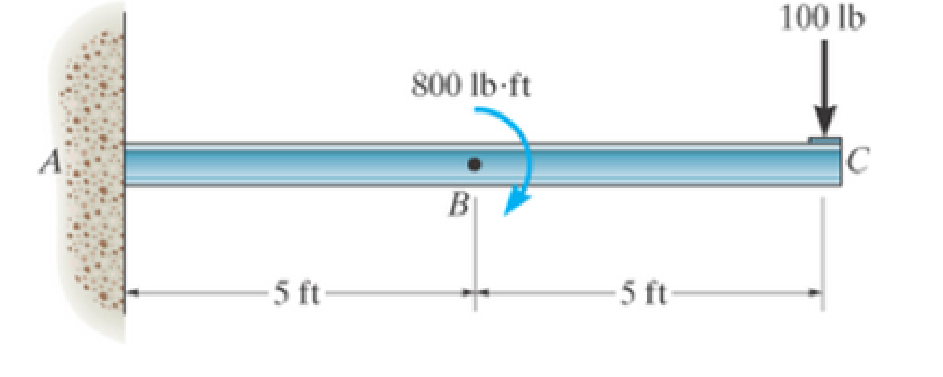
Prob. 7–48
Expert Solution & Answer

Learn your wayIncludes step-by-step video

schedule07:50
Students have asked these similar questions
Problem (17): water flowing in an open channel of a rectangular cross-section with width (b) transitions from a
mild slope to a steep slope (i.e., from subcritical to supercritical flow) with normal water depths of (y₁) and
(y2), respectively.
Given the values of y₁ [m], y₂ [m], and b [m], calculate the discharge in the channel (Q) in [Lit/s].
Givens:
y1 = 4.112 m
y2 =
0.387 m
b = 0.942 m
Answers:
( 1 ) 1880.186 lit/s
( 2 ) 4042.945 lit/s
( 3 ) 2553.11 lit/s
( 4 ) 3130.448 lit/s
Problem (14): A pump is being used to lift water from an underground
tank through a pipe of diameter (d) at discharge (Q). The total head
loss until the pump entrance can be calculated as (h₁ = K[V²/2g]), h
where (V) is the flow velocity in the pipe. The elevation difference
between the pump and tank surface is (h).
Given the values of h [cm], d [cm], and K [-], calculate the maximum
discharge Q [Lit/s] beyond which cavitation would take place at the
pump entrance. Assume Turbulent flow conditions.
Givens:
h = 120.31 cm
d = 14.455 cm
K = 8.976
Q
Answers:
(1) 94.917 lit/s
(2) 49.048 lit/s
( 3 ) 80.722 lit/s
68.588 lit/s
4
Problem (13): A pump is being used to lift water from the bottom
tank to the top tank in a galvanized iron pipe at a discharge (Q).
The length and diameter of the pipe section from the bottom tank
to the pump are (L₁) and (d₁), respectively. The length and
diameter of the pipe section from the pump to the top tank are
(L2) and (d2), respectively.
Given the values of Q [L/s], L₁ [m], d₁ [m], L₂ [m], d₂ [m],
calculate total head loss due to friction (i.e., major loss) in the
pipe (hmajor-loss) in [cm].
Givens:
L₁,d₁
Pump
L₂,d2
오
0.533 lit/s
L1 =
6920.729 m
d1 =
1.065 m
L2 =
70.946 m
d2
0.072 m
Answers:
(1)
3.069 cm
(2) 3.914 cm
( 3 ) 2.519 cm
( 4 ) 1.855 cm
TABLE 8.1
Equivalent Roughness for New Pipes
Pipe
Riveted steel
Concrete
Wood stave
Cast iron
Galvanized iron
Equivalent Roughness, &
Feet
Millimeters
0.003-0.03 0.9-9.0
0.001-0.01 0.3-3.0
0.0006-0.003 0.18-0.9
0.00085
0.26
0.0005
0.15
0.045
0.000005
0.0015
0.0 (smooth) 0.0 (smooth)
Commercial steel or wrought iron 0.00015
Drawn…
Chapter 7 Solutions
Engineering Mechanics: Statics
Ch. 7.1 - Determine the normal force, shear force, and...Ch. 7.1 - Determine the normal force, shear force, and...Ch. 7.1 - Determine the normal force, shear force, and...Ch. 7.1 - Determine the normal force, shear force, and...Ch. 7.1 - Determine the normal force, shear force, and...Ch. 7.1 - Assume A is pinned and B is a roller. Prob. F7-6Ch. 7.1 - Assume the support at B is a roller. Point C is...Ch. 7.1 - Determine the shear force and moment at points C...Ch. 7.1 - If the suspended load has a weight of 2 kN and a...Ch. 7.1 - Prob. 4P
Ch. 7.1 - Prob. 5PCh. 7.1 - Determine the distance a as a fraction of the...Ch. 7.1 - Prob. 7PCh. 7.1 - Prob. 8PCh. 7.1 - Take P = 8 kN. Prob. 7-9Ch. 7.1 - Determine the largest vertical load P the frame...Ch. 7.1 - The shaft is supported by a journal bearing at A...Ch. 7.1 - Determine the internal normal force, shear force,...Ch. 7.1 - Prob. 13PCh. 7.1 - Prob. 14PCh. 7.1 - Prob. 15PCh. 7.1 - Prob. 16PCh. 7.1 - Prob. 17PCh. 7.1 - Point E is just to the right of the 3-kip load....Ch. 7.1 - Prob. 19PCh. 7.1 - Determine the internal normal force, shear force,...Ch. 7.1 - Prob. 21PCh. 7.1 - Prob. 22PCh. 7.1 - Prob. 23PCh. 7.1 - Determine the internal normal force, shear force,...Ch. 7.1 - Prob. 25PCh. 7.1 - Determine the ratio of a/b for which the shear...Ch. 7.1 - Prob. 27PCh. 7.1 - Prob. 28PCh. 7.1 - Determine the normal force, shear force, and...Ch. 7.1 - Determine the normal force, shear force, and...Ch. 7.1 - Prob. 31PCh. 7.1 - Prob. 32PCh. 7.1 - Prob. 33PCh. 7.1 - Prob. 34PCh. 7.1 - Prob. 35PCh. 7.1 - Prob. 36PCh. 7.1 - Prob. 37PCh. 7.1 - Prob. 38PCh. 7.1 - Prob. 39PCh. 7.1 - Prob. 40PCh. 7.1 - Determine the x, y, z components of force and...Ch. 7.1 - z components of force and moment at point C in the...Ch. 7.1 - Prob. 43PCh. 7.1 - Prob. 44PCh. 7.2 - Determine the shear and moment as a function of x,...Ch. 7.2 - Determine the shear and moment as a function of x,...Ch. 7.2 - Determine the shear and moment as a function of x,...Ch. 7.2 - Determine the shear and moment as a function of x,...Ch. 7.2 - Determine the shear and moment as a function of x,...Ch. 7.2 - Determine the shear and moment as a function of x,...Ch. 7.2 - Prob. 45PCh. 7.2 - Draw the shear and moment diagrams for the beam...Ch. 7.2 - Draw the shear and moment diagrams for the beam...Ch. 7.2 - Draw the shear and moment diagrams of the beam (a)...Ch. 7.2 - If L = 9 m, the beam will fail when the maximum...Ch. 7.2 - Draw the shear and moment diagrams for the...Ch. 7.2 - Prob. 51PCh. 7.2 - Prob. 52PCh. 7.2 - Draw the shear and moment diagrams for the beam....Ch. 7.2 - Prob. 54PCh. 7.2 - Draw the shear and bending-moment diagrams for the...Ch. 7.2 - Prob. 56PCh. 7.2 - Draw the shear and bending-moment diagrams for...Ch. 7.2 - Draw the shear and moment diagrams for the...Ch. 7.2 - Prob. 59PCh. 7.2 - The shaft is supported by a smooth thrust bearing...Ch. 7.2 - Prob. 61PCh. 7.2 - Prob. 62PCh. 7.2 - Prob. 63PCh. 7.2 - Prob. 64PCh. 7.2 - Prob. 65PCh. 7.2 - Draw the shear and moment diagrams for the beam....Ch. 7.2 - Prob. 67PCh. 7.2 - Prob. 68PCh. 7.2 - Express the internal shear and moment components...Ch. 7.3 - Draw the shear and moment diagrams for the beam....Ch. 7.3 - Draw the shear and moment diagrams for the beam....Ch. 7.3 - Draw the shear and moment diagrams for the beam....Ch. 7.3 - Draw the shear and moment diagrams for the beam....Ch. 7.3 - Draw the shear and moment diagrams for the beam....Ch. 7.3 - Draw the shear and moment diagrams for the beam....Ch. 7.3 - Prob. 70PCh. 7.3 - Prob. 71PCh. 7.3 - Draw the shear and moment diagrams for the beam....Ch. 7.3 - Prob. 73PCh. 7.3 - Draw the shear and moment diagrams for the...Ch. 7.3 - Draw the shear and moment diagrams for the beam....Ch. 7.3 - Prob. 76PCh. 7.3 - Prob. 77PCh. 7.3 - Draw the shear and moment diagrams for the shaft....Ch. 7.3 - Draw the shear and moment diagrams for the beam....Ch. 7.3 - Prob. 80PCh. 7.3 - Prob. 81PCh. 7.3 - Prob. 82PCh. 7.3 - Prob. 83PCh. 7.3 - Prob. 84PCh. 7.3 - Prob. 85PCh. 7.3 - Prob. 86PCh. 7.3 - Prob. 87PCh. 7.3 - Prob. 88PCh. 7.3 - Prob. 89PCh. 7.3 - Prob. 90PCh. 7.3 - Prob. 91PCh. 7.3 - Prob. 92PCh. 7.3 - Prob. 93PCh. 7.4 - Prob. 94PCh. 7.4 - Prob. 95PCh. 7.4 - Determine the tension in each segment of the cable...Ch. 7.4 - Prob. 97PCh. 7.4 - Prob. 98PCh. 7.4 - Prob. 99PCh. 7.4 - If cylinder E has a mass of 20 kg and each cable...Ch. 7.4 - Prob. 101PCh. 7.4 - Prob. 102PCh. 7.4 - If yB = 1.5 ft. determine the largest weight of...Ch. 7.4 - The cable AB is subjected to a uniform loading of...Ch. 7.4 - Determine the maximum uniform loading w, measured...Ch. 7.4 - The cable is subjected to a uniform loading of w =...Ch. 7.4 - Prob. 107PCh. 7.4 - Prob. 108PCh. 7.4 - If the pipe has a mass per unit length of 1500...Ch. 7.4 - Prob. 110PCh. 7.4 - Prob. 111PCh. 7.4 - Prob. 112PCh. 7.4 - Prob. 113PCh. 7.4 - A telephone line (cable) stretches between two...Ch. 7.4 - Prob. 115PCh. 7.4 - Prob. 116PCh. 7.4 - Prob. 117PCh. 7.4 - A cable has a weight of 5 lb/ft. If it can span...Ch. 7.4 - Prob. 119PCh. 7.4 - The power transmission cable weighs 10 lb/fl. If...Ch. 7.4 - The power transmission cable weighs 10 lb/ft. If h...Ch. 7.4 - Prob. 122PCh. 7.4 - Prob. 123PCh. 7.4 - The man picks up the 52-ft chain and holds it just...Ch. 7.4 - Determine the internal normal force, shear force,...Ch. 7.4 - Draw the shear and moment diagrams for the beam....Ch. 7.4 - Prob. 127RPCh. 7.4 - Prob. 128RPCh. 7.4 - Prob. 129RPCh. 7.4 - Prob. 130RPCh. 7.4 - Prob. 131RPCh. 7.4 - Prob. 132RPCh. 7.4 - Draw the shear and moment diagrams for the beam....Ch. 7.4 - Determine the normal force, shear force, and...Ch. 7.4 - Draw the shear and moment diagrams for the beam....Ch. 7.4 - Prob. 137RPCh. 7.4 - Prob. 138RPCh. 7.4 - Prob. 139RP
Additional Engineering Textbook Solutions
Find more solutions based on key concepts
Describe a method that can be used to gather a piece of data such as the users age.
Web Development and Design Foundations with HTML5 (8th Edition)
Describe the differences between the injection molding of plastics and the injection molding of ceramics.
Degarmo's Materials And Processes In Manufacturing
(Instance Variables) Explain the purpose of an instance variable.
Java How to Program, Early Objects (11th Edition) (Deitel: How to Program)
Translate the following Python program into the Vole machine language described in Appendix C. X = 0 while (X ...
Computer Science: An Overview (13th Edition) (What's New in Computer Science)
2-1 List the five types of measurements that form the
basis of traditional ptane surveying-
Elementary Surveying: An Introduction To Geomatics (15th Edition)
Suppose aList is an object of the class ArrayListString. How do you add the string Hello to the end of aList ?
Java: An Introduction to Problem Solving and Programming (8th Edition)
Knowledge Booster


Learn more about
Need a deep-dive on the concept behind this application? Look no further. Learn more about this topic, mechanical-engineering and related others by exploring similar questions and additional content below.Similar questions
- The flow rate is 12.275 Liters/s and the diameter is 6.266 cm.arrow_forwardAn experimental setup is being built to study the flow in a large water main (i.e., a large pipe). The water main is expected to convey a discharge (Qp). The experimental tube will be built at a length scale of 1/20 of the actual water main. After building the experimental setup, the pressure drop per unit length in the model tube (APm/Lm) is measured. Problem (20): Given the value of APm/Lm [kPa/m], and assuming pressure coefficient similitude, calculate the drop in the pressure per unit length of the water main (APP/Lp) in [Pa/m]. Givens: AP M/L m = 590.637 kPa/m meen Answers: ( 1 ) 59.369 Pa/m ( 2 ) 73.83 Pa/m (3) 95.443 Pa/m ( 4 ) 44.444 Pa/m *******arrow_forwardFind the reaction force in y if Ain = 0.169 m^2, Aout = 0.143 m^2, p_in = 0.552 atm, Q = 0.367 m^3/s, α = 31.72 degrees. The pipe is flat on the ground so do not factor in weight of the pipe and fluid.arrow_forward
- Find the reaction force in x if Ain = 0.301 m^2, Aout = 0.177 m^2, p_in = 1.338 atm, Q = 0.669 m^3/s, and α = 37.183 degreesarrow_forwardProblem 5: Three-Force Equilibrium A structural connection at point O is in equilibrium under the action of three forces. • • . Member A applies a force of 9 kN vertically upward along the y-axis. Member B applies an unknown force F at the angle shown. Member C applies an unknown force T along its length at an angle shown. Determine the magnitudes of forces F and T required for equilibrium, assuming 0 = 90° y 9 kN Aarrow_forwardProblem 19: Determine the force in members HG, HE, and DE of the truss, and state if the members are in tension or compression. 4 ft K J I H G B C D E F -3 ft -3 ft 3 ft 3 ft 3 ft- 1500 lb 1500 lb 1500 lb 1500 lb 1500 lbarrow_forward
- Problem 14: Determine the reactions at the pin A, and the tension in cord. Neglect the thickness of the beam. F1=26kN F2 13 12 80° -2m 3marrow_forwardProblem 22: Determine the force in members GF, FC, and CD of the bridge truss and state if the members are in tension or compression. F 15 ft B D -40 ft 40 ft -40 ft 40 ft- 5 k 10 k 15 k 30 ft Earrow_forwardProblem 20: Determine the force in members BC, HC, and HG. After the truss is sectioned use a single equation of equilibrium for the calculation of each force. State if the members are in tension or compression. 5 kN 4 kN 4 kN 3 kN 2 kN B D E F 3 m -5 m- -5 m- 5 m 5 m-arrow_forward
- An experimental setup is being built to study the flow in a large water main (i.e., a large pipe). The water main is expected to convey a discharge (Qp). The experimental tube will be built at a length scale of 1/20 of the actual water main. After building the experimental setup, the pressure drop per unit length in the model tube (APm/Lm) is measured. Problem (19): Given the value of Qp [m³/s], and assuming Reynolds number similitude between the water main and experimental tube, calculate the flow rate in the model tube (Qm) in [lit/s]. = 30.015 m^3/sarrow_forwardProblem 11: The lamp has a weight of 15 lb and is supported by the six cords connected together as shown. Determine the tension in each cord and the angle 0 for equilibrium. Cord BC is horizontal. E 30° B 60° Aarrow_forwardProblem 10: If the bucket weighs 50 lb, determine the tension developed in each of the wires. B $30° 5 E D 130°arrow_forward
arrow_back_ios
SEE MORE QUESTIONS
arrow_forward_ios
Recommended textbooks for you
 Elements Of ElectromagneticsMechanical EngineeringISBN:9780190698614Author:Sadiku, Matthew N. O.Publisher:Oxford University Press
 Mechanics of Materials (10th Edition)Mechanical EngineeringISBN:9780134319650Author:Russell C. HibbelerPublisher:PEARSON
 Thermodynamics: An Engineering ApproachMechanical EngineeringISBN:9781259822674Author:Yunus A. Cengel Dr., Michael A. BolesPublisher:McGraw-Hill Education
 Control Systems EngineeringMechanical EngineeringISBN:9781118170519Author:Norman S. NisePublisher:WILEY
 Mechanics of Materials (MindTap Course List)Mechanical EngineeringISBN:9781337093347Author:Barry J. Goodno, James M. GerePublisher:Cengage Learning
 Engineering Mechanics: StaticsMechanical EngineeringISBN:9781118807330Author:James L. Meriam, L. G. Kraige, J. N. BoltonPublisher:WILEY
Elements Of Electromagnetics
Mechanical Engineering
ISBN:9780190698614
Author:Sadiku, Matthew N. O.
Publisher:Oxford University Press
Mechanics of Materials (10th Edition)
Mechanical Engineering
ISBN:9780134319650
Author:Russell C. Hibbeler
Publisher:PEARSON
Thermodynamics: An Engineering Approach
Mechanical Engineering
ISBN:9781259822674
Author:Yunus A. Cengel Dr., Michael A. Boles
Publisher:McGraw-Hill Education
Control Systems Engineering
Mechanical Engineering
ISBN:9781118170519
Author:Norman S. Nise
Publisher:WILEY
Mechanics of Materials (MindTap Course List)
Mechanical Engineering
ISBN:9781337093347
Author:Barry J. Goodno, James M. Gere
Publisher:Cengage Learning
Engineering Mechanics: Statics
Mechanical Engineering
ISBN:9781118807330
Author:James L. Meriam, L. G. Kraige, J. N. Bolton
Publisher:WILEY
Understanding Shear Force and Bending Moment Diagrams; Author: The Efficient Engineer;https://www.youtube.com/watch?v=C-FEVzI8oe8;License: Standard YouTube License, CC-BY
Bending Stress; Author: moodlemech;https://www.youtube.com/watch?v=9QIqewkE6xM;License: Standard Youtube License