
Engineering Mechanics: Statics
13th Edition
ISBN: 9780132915540
Author: Russell C. Hibbeler
Publisher: Prentice Hall
expand_more
expand_more
format_list_bulleted
Concept explainers
Videos
Textbook Question
Chapter 7.4, Problem 133RP
Draw the shear and moment diagrams for the beam.
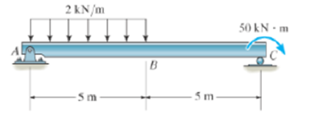
Prob. R7-5
Expert Solution & Answer
Want to see the full answer?
Check out a sample textbook solution
Students have asked these similar questions
Using the Maxwell relations, determine a relation for
equation of state is (P-a/v²) (v−b) = RT.
Os
for a gas whose
av T
(◉
Homework#8
Homework#8
Chapter 7 Solutions
Engineering Mechanics: Statics
Ch. 7.1 - Determine the normal force, shear force, and...Ch. 7.1 - Determine the normal force, shear force, and...Ch. 7.1 - Determine the normal force, shear force, and...Ch. 7.1 - Determine the normal force, shear force, and...Ch. 7.1 - Determine the normal force, shear force, and...Ch. 7.1 - Assume A is pinned and B is a roller. Prob. F7-6Ch. 7.1 - Assume the support at B is a roller. Point C is...Ch. 7.1 - Determine the shear force and moment at points C...Ch. 7.1 - If the suspended load has a weight of 2 kN and a...Ch. 7.1 - Prob. 4P
Ch. 7.1 - Prob. 5PCh. 7.1 - Determine the distance a as a fraction of the...Ch. 7.1 - Prob. 7PCh. 7.1 - Prob. 8PCh. 7.1 - Take P = 8 kN. Prob. 7-9Ch. 7.1 - Determine the largest vertical load P the frame...Ch. 7.1 - The shaft is supported by a journal bearing at A...Ch. 7.1 - Determine the internal normal force, shear force,...Ch. 7.1 - Prob. 13PCh. 7.1 - Prob. 14PCh. 7.1 - Prob. 15PCh. 7.1 - Prob. 16PCh. 7.1 - Prob. 17PCh. 7.1 - Point E is just to the right of the 3-kip load....Ch. 7.1 - Prob. 19PCh. 7.1 - Determine the internal normal force, shear force,...Ch. 7.1 - Prob. 21PCh. 7.1 - Prob. 22PCh. 7.1 - Prob. 23PCh. 7.1 - Determine the internal normal force, shear force,...Ch. 7.1 - Prob. 25PCh. 7.1 - Determine the ratio of a/b for which the shear...Ch. 7.1 - Prob. 27PCh. 7.1 - Prob. 28PCh. 7.1 - Determine the normal force, shear force, and...Ch. 7.1 - Determine the normal force, shear force, and...Ch. 7.1 - Prob. 31PCh. 7.1 - Prob. 32PCh. 7.1 - Prob. 33PCh. 7.1 - Prob. 34PCh. 7.1 - Prob. 35PCh. 7.1 - Prob. 36PCh. 7.1 - Prob. 37PCh. 7.1 - Prob. 38PCh. 7.1 - Prob. 39PCh. 7.1 - Prob. 40PCh. 7.1 - Determine the x, y, z components of force and...Ch. 7.1 - z components of force and moment at point C in the...Ch. 7.1 - Prob. 43PCh. 7.1 - Prob. 44PCh. 7.2 - Determine the shear and moment as a function of x,...Ch. 7.2 - Determine the shear and moment as a function of x,...Ch. 7.2 - Determine the shear and moment as a function of x,...Ch. 7.2 - Determine the shear and moment as a function of x,...Ch. 7.2 - Determine the shear and moment as a function of x,...Ch. 7.2 - Determine the shear and moment as a function of x,...Ch. 7.2 - Prob. 45PCh. 7.2 - Draw the shear and moment diagrams for the beam...Ch. 7.2 - Draw the shear and moment diagrams for the beam...Ch. 7.2 - Draw the shear and moment diagrams of the beam (a)...Ch. 7.2 - If L = 9 m, the beam will fail when the maximum...Ch. 7.2 - Draw the shear and moment diagrams for the...Ch. 7.2 - Prob. 51PCh. 7.2 - Prob. 52PCh. 7.2 - Draw the shear and moment diagrams for the beam....Ch. 7.2 - Prob. 54PCh. 7.2 - Draw the shear and bending-moment diagrams for the...Ch. 7.2 - Prob. 56PCh. 7.2 - Draw the shear and bending-moment diagrams for...Ch. 7.2 - Draw the shear and moment diagrams for the...Ch. 7.2 - Prob. 59PCh. 7.2 - The shaft is supported by a smooth thrust bearing...Ch. 7.2 - Prob. 61PCh. 7.2 - Prob. 62PCh. 7.2 - Prob. 63PCh. 7.2 - Prob. 64PCh. 7.2 - Prob. 65PCh. 7.2 - Draw the shear and moment diagrams for the beam....Ch. 7.2 - Prob. 67PCh. 7.2 - Prob. 68PCh. 7.2 - Express the internal shear and moment components...Ch. 7.3 - Draw the shear and moment diagrams for the beam....Ch. 7.3 - Draw the shear and moment diagrams for the beam....Ch. 7.3 - Draw the shear and moment diagrams for the beam....Ch. 7.3 - Draw the shear and moment diagrams for the beam....Ch. 7.3 - Draw the shear and moment diagrams for the beam....Ch. 7.3 - Draw the shear and moment diagrams for the beam....Ch. 7.3 - Prob. 70PCh. 7.3 - Prob. 71PCh. 7.3 - Draw the shear and moment diagrams for the beam....Ch. 7.3 - Prob. 73PCh. 7.3 - Draw the shear and moment diagrams for the...Ch. 7.3 - Draw the shear and moment diagrams for the beam....Ch. 7.3 - Prob. 76PCh. 7.3 - Prob. 77PCh. 7.3 - Draw the shear and moment diagrams for the shaft....Ch. 7.3 - Draw the shear and moment diagrams for the beam....Ch. 7.3 - Prob. 80PCh. 7.3 - Prob. 81PCh. 7.3 - Prob. 82PCh. 7.3 - Prob. 83PCh. 7.3 - Prob. 84PCh. 7.3 - Prob. 85PCh. 7.3 - Prob. 86PCh. 7.3 - Prob. 87PCh. 7.3 - Prob. 88PCh. 7.3 - Prob. 89PCh. 7.3 - Prob. 90PCh. 7.3 - Prob. 91PCh. 7.3 - Prob. 92PCh. 7.3 - Prob. 93PCh. 7.4 - Prob. 94PCh. 7.4 - Prob. 95PCh. 7.4 - Determine the tension in each segment of the cable...Ch. 7.4 - Prob. 97PCh. 7.4 - Prob. 98PCh. 7.4 - Prob. 99PCh. 7.4 - If cylinder E has a mass of 20 kg and each cable...Ch. 7.4 - Prob. 101PCh. 7.4 - Prob. 102PCh. 7.4 - If yB = 1.5 ft. determine the largest weight of...Ch. 7.4 - The cable AB is subjected to a uniform loading of...Ch. 7.4 - Determine the maximum uniform loading w, measured...Ch. 7.4 - The cable is subjected to a uniform loading of w =...Ch. 7.4 - Prob. 107PCh. 7.4 - Prob. 108PCh. 7.4 - If the pipe has a mass per unit length of 1500...Ch. 7.4 - Prob. 110PCh. 7.4 - Prob. 111PCh. 7.4 - Prob. 112PCh. 7.4 - Prob. 113PCh. 7.4 - A telephone line (cable) stretches between two...Ch. 7.4 - Prob. 115PCh. 7.4 - Prob. 116PCh. 7.4 - Prob. 117PCh. 7.4 - A cable has a weight of 5 lb/ft. If it can span...Ch. 7.4 - Prob. 119PCh. 7.4 - The power transmission cable weighs 10 lb/fl. If...Ch. 7.4 - The power transmission cable weighs 10 lb/ft. If h...Ch. 7.4 - Prob. 122PCh. 7.4 - Prob. 123PCh. 7.4 - The man picks up the 52-ft chain and holds it just...Ch. 7.4 - Determine the internal normal force, shear force,...Ch. 7.4 - Draw the shear and moment diagrams for the beam....Ch. 7.4 - Prob. 127RPCh. 7.4 - Prob. 128RPCh. 7.4 - Prob. 129RPCh. 7.4 - Prob. 130RPCh. 7.4 - Prob. 131RPCh. 7.4 - Prob. 132RPCh. 7.4 - Draw the shear and moment diagrams for the beam....Ch. 7.4 - Determine the normal force, shear force, and...Ch. 7.4 - Draw the shear and moment diagrams for the beam....Ch. 7.4 - Prob. 137RPCh. 7.4 - Prob. 138RPCh. 7.4 - Prob. 139RP
Knowledge Booster


Learn more about
Need a deep-dive on the concept behind this application? Look no further. Learn more about this topic, mechanical-engineering and related others by exploring similar questions and additional content below.Similar questions
- Box A has a mass of 15 kilograms and is attached to the 20 kilogram Box B using the cord and pulley system shown. The coefficient of kinetic friction between the boxes and surface is 0.2 and the moment of inertia of the pulley is 0.5 kg * m^ 2. After 2 seconds, how far do the boxes move? A бро Barrow_forwardBox A has a mass of 15 kilograms and is attached to the 20 kilogram Box B using the cord and pulley system shown. The coefficient of kinetic friction between the boxes and surface is 0.2 and the moment of inertia of the pulley is 0.5 kg * m^2. Both boxes are 0.25 m long and 0.25 m high. The cord is attached to the bottom of Box A and the middle of box B. After 2 seconds, how far do the boxes move? A From бро Barrow_forwardHomework#8arrow_forwardSign in PDF Lecture W09.pdf PDF MMB241 - Tutorial L9.pdf File C:/Users/KHULEKANI/Desktop/mmb241/MMB241%20-%20Tutorial%20L9.pdf II! Draw | I│Alla | Ask Copilot + of 4 D Topic: Kinetics of Particles: - Forces in dynamic system, Free body diagram, newton's laws of motion, and equations of motion. TQ1. The 10-kg block is subjected to the forces shown. In each case, determine its velocity when t=2s if v 0 when t=0 500 N F = (201) N 300 N (b) TQ2. The 10-kg block is subjected to the forces shown. In each case, determine its velocity at s-8 m if v = 3 m/s at s=0. Motion occurs to the right. 40 N F = (2.5 s) N 200 N 30 N (b) TQ3. Determine the initial acceleration of the 10-kg smooth collar. The spring has an unstretched length of 1 m. 1 σ Q ☆ Q 6 ا الى ☑arrow_forwardSign in PDF Lecture W09.pdf PDF MMB241 - Tutorial L9.pdf File C:/Users/KHULEKANI/Desktop/mmb241/MMB241%20-%20Tutorial%20L9.pdf II! Draw | I│Alla | Ask Copilot + 4 of 4 | D TQ9. If motor M exerts a force of F (10t 2 + 100) N determine the velocity of the 25-kg crate when t kinetic friction between the crate and the plane are μs The crate is initially at rest. on the cable, where t is in seconds, 4s. The coefficients of static and 0.3 and μk = 0.25, respectively. M 3 TQ10. The spring has a stiffness k = 200 N/m and is unstretched when the 25-kg block is at A. Determine the acceleration of the block when s = 0.4 m. The contact surface between the block and the plane is smooth. 0.3 m F= 100 N F= 100 N k = 200 N/m σ Q Q ☆ ا الى 6 ☑arrow_forwardmy ID# is 016948724 please solve this problem step by steparrow_forwardMY ID#016948724 please solve the problem step by spetarrow_forward1 8 4 For the table with 4×4 rows and columns as shown Add numbers so that the sum of any row or column equals .30 Use only these numbers: .1.2.3.4.5.6.10.11.12.12.13.14.14arrow_forwardMY ID# 016948724 please solve this problem step by steparrow_forwardThe pickup truck weighs 3220 Ib and reaches a speed of 30 mi/hr from rest in a distance of 200 ft up the 10-percent incline with constant acceleration. Calculate the normal force under each pair of wheels and the friction force under the rear driving wheels. The effective coefficient of friction between the tires and the road is known to be at least 0.8.arrow_forward1. The figure shows a car jack to support 400kg (W=400kg). In the drawing, the angle (0) varies between 15 and 70 °. The links are machined from AISI 1020 hot-rolled steel bars with a minimum yield strength of 380MPa. Each link consists of two bars, one on each side of the central bearings. The bars are 300mm in length (/) and 25 mm in width (w). The pinned ends have the buckling constant (C) of 1.4 for out of plane buckling. The design factor (nd) is 2.5. (1) Find the thickness (t) of the bars and the factor of safety (n). (2) Check if the bar is an Euler beam. Darrow_forward(Read image)arrow_forwardarrow_back_iosSEE MORE QUESTIONSarrow_forward_ios
Recommended textbooks for you
 Elements Of ElectromagneticsMechanical EngineeringISBN:9780190698614Author:Sadiku, Matthew N. O.Publisher:Oxford University Press
 Mechanics of Materials (10th Edition)Mechanical EngineeringISBN:9780134319650Author:Russell C. HibbelerPublisher:PEARSON
 Thermodynamics: An Engineering ApproachMechanical EngineeringISBN:9781259822674Author:Yunus A. Cengel Dr., Michael A. BolesPublisher:McGraw-Hill Education
 Control Systems EngineeringMechanical EngineeringISBN:9781118170519Author:Norman S. NisePublisher:WILEY
 Mechanics of Materials (MindTap Course List)Mechanical EngineeringISBN:9781337093347Author:Barry J. Goodno, James M. GerePublisher:Cengage Learning
 Engineering Mechanics: StaticsMechanical EngineeringISBN:9781118807330Author:James L. Meriam, L. G. Kraige, J. N. BoltonPublisher:WILEY
Elements Of Electromagnetics
Mechanical Engineering
ISBN:9780190698614
Author:Sadiku, Matthew N. O.
Publisher:Oxford University Press
Mechanics of Materials (10th Edition)
Mechanical Engineering
ISBN:9780134319650
Author:Russell C. Hibbeler
Publisher:PEARSON
Thermodynamics: An Engineering Approach
Mechanical Engineering
ISBN:9781259822674
Author:Yunus A. Cengel Dr., Michael A. Boles
Publisher:McGraw-Hill Education
Control Systems Engineering
Mechanical Engineering
ISBN:9781118170519
Author:Norman S. Nise
Publisher:WILEY
Mechanics of Materials (MindTap Course List)
Mechanical Engineering
ISBN:9781337093347
Author:Barry J. Goodno, James M. Gere
Publisher:Cengage Learning
Engineering Mechanics: Statics
Mechanical Engineering
ISBN:9781118807330
Author:James L. Meriam, L. G. Kraige, J. N. Bolton
Publisher:WILEY
Understanding Shear Force and Bending Moment Diagrams; Author: The Efficient Engineer;https://www.youtube.com/watch?v=C-FEVzI8oe8;License: Standard YouTube License, CC-BY
Bending Stress; Author: moodlemech;https://www.youtube.com/watch?v=9QIqewkE6xM;License: Standard Youtube License