
Concept explainers
Videos
(a)
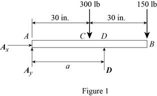
The distance a from the ends of the beam to the points where the cables should be attached if the maximum absolute value of the bending moment in the beam AB is the smallest.
(a)
Answer to Problem 7.61P
The distance a from the ends of the beam to the points where the cables should be attached if the maximum absolute value of the bending moment in the beam AB is the smallest is
Explanation of Solution
Refer Figure 1.
Write an expression to calculate the counter clockwise moment at point A.
Here,
Write an expression to calculate the counter clockwise moment at point A.
Here,
Write an expression to calculate the counter clockwise moment at point A.
Here,
Conclusion:
Refer Figure 1:
Calculate the moment about point A.
Here,
Rearrange the equation to calculate the D.
Substitute
Refer Figure 2.

Calculate the moment about point C.
Rearrange the equation to calculate the
Substitute
Refer Figure 2.
Calculate the moment about point D.
Rearrange the equation to calculate the
Substitute
The magnitude of the maximum moment is equal to the magnitude of the minimum moment.
Substitute (I) and (II) in above equation to find a.
Rearrange the equation to find a.
Thus, the distance a from the ends of the beam to the points where the cables should be attached if the maximum absolute value of the bending moment in the beam AB is the smallest is
(b)
The value of
(b)
Answer to Problem 7.61P
The value of
Explanation of Solution
Refer Figure 4.
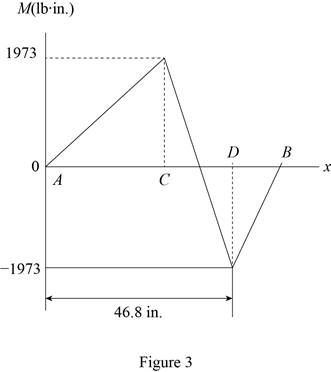
The magnitude of the maximum moment is equal to the magnitude of the minimum moment.
Conclusion:
Substitute
Thus, the value of
Want to see more full solutions like this?
Chapter 7 Solutions
VECTOR MECHANIC


- Problem 1: For each of the following images, draw a complete FBD and KD for the specified objects. Then write the equations of motion using variables for all unknowns (e.g., mass, friction coefficient, etc.), plugging in kinematic expressions and simplifying where appropriate. Assume motion in all cases, so any friction would be kinetic. M (a) Blocks A & B (Be careful with acceleration of B relative to accelerating block A) 30° (b) Block A being pulled up my motor M (use rotated rectangular coordinate system) 20° (c) Ball at C, top of swing (use path coordinates) (d) Parasailer/Person (use polar coordinates)arrow_forwardwhere M1=0.41m, M2=1.8m, M3=0.56m, please use bernoulis equation where necessary and The solutions should include, but not be limited to, the equations used tosolve the problems, the charts used to solve the problems, detailed working,choice of variables, the control volume considered, justification anddiscussion of results etc.If determining the friction factor, the use of both Moody chart and empiricalequations should be used to verify the validity of the value.arrow_forwardQ3. The attachment shown in Fig.2 is made of 1040 HR. Design the weldment (give the pattern, electrode number, type of weld, length of weld, and leg size). All dimensions in mm 120 Fig.2 12 17 b =7.5 5 kN 60 60°arrow_forward
- Solve this problem and show all of the workarrow_forwardarch Moving to año Question 5 The head-vs-capacity curves for two centrifugal pumps A and B are shown below: Which of the following is a correct statement at a flow rate of 600 ft3/min? Assuming a pump efficiency of 80%. Head [ft] 50 45. 40 CHE 35. 30 25 20 PR 64°F Cloudy 4arrow_forwardI need help with a MATLAB code. I am trying to implement algorithm 3 and 4 as shown in the image. I am getting some size errors. Can you help me fix the code. clc; clear all; % Define initial conditions and parameters r0 = [1000, 0, 0]; % Initial position in meters v0 = [0, 10, 0]; % Initial velocity in m/s m0 = 1000; % Initial mass in kg z0 = log(m0); % Initial mass logarithm a0 = [0, 0, 1]; % Initial thrust direction in m/s^2 (thrust in z-direction) sigma0 = 0.1; % Initial thrust magnitude divided by mass % Initial state vector x0 = [r0, v0, z0] x0 = [r0, v0, z0]; % Initial control input u0 = [a0, sigma0] u0 = [a0, sigma0]; % Time span for integration t0 = 0; % Initial time tf = 10; % Final time N = 100; % Number of time steps dt = (tf - t0) / N; % Time step size t_span = linspace(t0, tf, N); % Discretized time vector % Solve the system of equations using ode45 [t, Y] = ode45(@(t, Y) EoMwithDiscreteMatrix(t, Y, u0, x0, t0, tf), t_span, x0); % Compute the matrices A_k,…arrow_forward
- Q2) Determine the thickness of weld (h) for the figure shown below. when the Su= 410 MPa and factor of safety of 2. COR 50 200 60 F=2000Narrow_forwardPlease draw front, top and side view, in AutoCAD both of themarrow_forwardQuestion 7 A well is pumped from a confined aquifer at a constant rate of 1000 gallons per minute (gpm). The following data were collected during the pumping test: . Distance from the well to the observation well (r) = 150 feet Differential drawdown (Ah) in the observation well at this distance = 2.5 feet Aquifer properties: Transmissivity (T) = 25,000 gpd/ft • Storativity (S)- 0.0005 (dimensionless) Pumping time (t) = 5 hours Watch your units !! Using the above information, calculate the drawdown (h) in feet in the observation well at a distance of 150 feet after 5 hours of pumping. (Use the powerpoint slides for approximations for the well function W(u).arrow_forward
 Elements Of ElectromagneticsMechanical EngineeringISBN:9780190698614Author:Sadiku, Matthew N. O.Publisher:Oxford University Press
 Mechanics of Materials (10th Edition)Mechanical EngineeringISBN:9780134319650Author:Russell C. HibbelerPublisher:PEARSON
 Thermodynamics: An Engineering ApproachMechanical EngineeringISBN:9781259822674Author:Yunus A. Cengel Dr., Michael A. BolesPublisher:McGraw-Hill Education
 Control Systems EngineeringMechanical EngineeringISBN:9781118170519Author:Norman S. NisePublisher:WILEY
 Mechanics of Materials (MindTap Course List)Mechanical EngineeringISBN:9781337093347Author:Barry J. Goodno, James M. GerePublisher:Cengage Learning
 Engineering Mechanics: StaticsMechanical EngineeringISBN:9781118807330Author:James L. Meriam, L. G. Kraige, J. N. BoltonPublisher:WILEY