Concept explainers
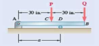
Knowing that P = Q = 150 lb, determine (a) the distance a for which the maximum absolute value of the bending moment in beam AB is as small as possible, (b) the corresponding value of |M|max. (See the hint for Prob. 7.55.)

Fig. P7.60
(a)
The distance a from the ends of the beam to the points where the cables should be attached if the maximum absolute value of the bending moment in the beam AB is the smallest.
Answer to Problem 7.60P
The distance a from the ends of the beam to the points where the cables should be attached if the maximum absolute value of the bending moment in the beam AB is the smallest is
Explanation of Solution
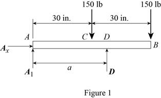
Refer Figures 1.

Write an expression to calculate the counter clockwise moment at point A.
Here,
Write an expression to calculate the counter clockwise moment at point A.
Here,
Write an expression to calculate the counter clockwise moment at point A.
Here,
Conclusion:
Refer Figure 1:
Calculate the moment about point A.
Here,
Rearrange the equation to calculate the D.
Substitute
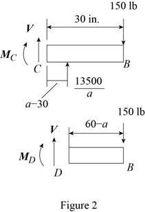
Refer figure 2.

Calculate the moment about point C.
Rearrange the equation to calculate the
Substitute
Refer figure 2.
Calculate the moment about point D.
Rearrange the equation to calculate the
Substitute
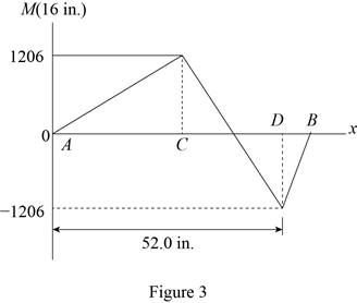
The magnitude of the maximum moment is equal to the magnitude of the minimum moment.
Substitute (I) and (II) in above equation to find a.
Rearrange the equation to find a.
Thus, the distance a from the ends of the beam to the points where the cables should be attached if the maximum absolute value of the bending moment in the beam AB is the smallest is
(b)
The value of
Answer to Problem 7.60P
The value of
Explanation of Solution
Refer figure 4.

The magnitude of the maximum moment is equal to the magnitude of the minimum moment.
Conclusion:
Substitute
Thus, the value of
Want to see more full solutions like this?
Chapter 7 Solutions
VECTOR MECHANIC
- Two squirrels are sitting on the rope as shown. The squirrel at A has a weight of 1.2 lb. The squirrel at B found less food this season and has a weight of 0.8 lb. The angles 0 and > are equal to 50° and 60° respectively. Determine the tension force in each of the rope segments (T₁ in segment, T₂ in segment Я, and T3 in segment DD) as well as the angle a in degrees. Ө A α B Note the figure may not be to scale. T₁ = lb lb T2 T3 = = lb απ deg A BY NC SA 2013 Michael Swanbomarrow_forwardEach cord can sustain a maximum tension of 500 N. Determine the largest mass of pipe that can be supported. B 60° A E Harrow_forward2. Link BD consists of a single bar 1 in. wide and 0.5 in. thick. Knowing that each pin has a in. diameter, determine (a) the maximum value of the normal stress in link BD and the bearing stress in link BD if 0 = 0, (b) the maximum value of the normal stress in link BD if 0 = 90. -6 in.- 12 in. 30° D 4 kipsarrow_forward
- In the image is a right rectangular pyramid of total mass m. Note the location of point Q. Determine the inertia dyadic for the pyramid P, relative to point Q for e hat unit vectors.arrow_forwardauto controlsarrow_forwardI am having a hard time solving for the vector v in the equation in the image. Can you help me?arrow_forward
- A 4 ft 300 Ib 1000 Ib.ft 350 Ib C 2 ft 3. 45° 250 Ib B. 3ft B 25ft 200 Ib 150 Ib Replace the force system acting on the frame shown in the figure by a resultant force (magnitude and direction), and specify where its line of action intersects member (AB), measured from point (A).arrow_forwardCan you research the standard percentage of Steam Quality in:(1.) Boiler - leaving boilerBoiler -> Out(2.) Condenser - coming in condenser In -> CondenserProvide reference Also define: steam quality, its purpose and importancearrow_forwardNumbers 1 and 2 and 5 are are optional problems. However, I only need the values (with units) of 3, 4 and 6. Thank you :)arrow_forward
 Elements Of ElectromagneticsMechanical EngineeringISBN:9780190698614Author:Sadiku, Matthew N. O.Publisher:Oxford University Press
 Mechanics of Materials (10th Edition)Mechanical EngineeringISBN:9780134319650Author:Russell C. HibbelerPublisher:PEARSON
 Thermodynamics: An Engineering ApproachMechanical EngineeringISBN:9781259822674Author:Yunus A. Cengel Dr., Michael A. BolesPublisher:McGraw-Hill Education
 Control Systems EngineeringMechanical EngineeringISBN:9781118170519Author:Norman S. NisePublisher:WILEY
 Mechanics of Materials (MindTap Course List)Mechanical EngineeringISBN:9781337093347Author:Barry J. Goodno, James M. GerePublisher:Cengage Learning
 Engineering Mechanics: StaticsMechanical EngineeringISBN:9781118807330Author:James L. Meriam, L. G. Kraige, J. N. BoltonPublisher:WILEY


