
Concept explainers
Videos
(a)
Plot the shear force and bending moment diagram for the beam.
Find the magnitude and location of the maximum absolute value of the bending moment.
(a)
Answer to Problem 7.161RP
The location and magnitude of the maximum absolute bending moment is
Explanation of Solution
Given information:
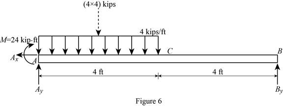
The moment applied at A is
Calculation:
Show the free-body diagram of the entire beam as in Figure 1.
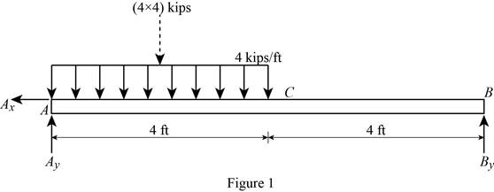
Find the vertical reaction at point B by taking moment about point A.
Find the vertical reaction at point A by reoslving the vertical component of forces.
Resolve the horizontal component of forces.
Consider the section AC:
Consider a section at a distance x from left end A.
Show the free-body diagram of the section as in Figure 2.
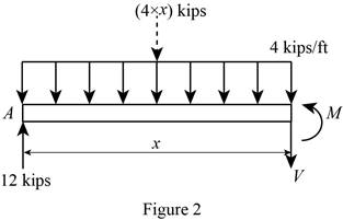
Resolve the vertical component of forces.
Take moment about the section.
At
Substitute 0 for x in Equation (1).
Substitute 0 for x in Equation (2).
At
Substitute 4 ft for x in Equation (1).
Substitute 4 ft for x in Equation (2).
Consider the section CB:
Show the free-body diagram of the section as in Figure 3.
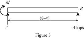
Resolve the vertical component of forces.
Take moment about the section.
At
Substitute 4 ft for x in Equation (3).
At
Substitute 8 ft for x in Equation (3).
Tabulate the shear force values as in Table 1.
| Location, x ft | Shear force, kips |
| 0 | 12 |
| 4 | –4 |
| 8 | –4 |
Plot the shear force diagram as in Figure 4.
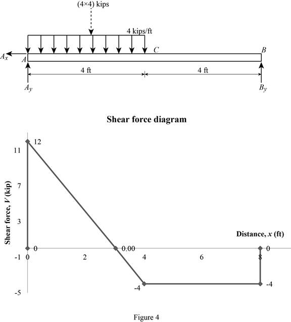
The maximum bending moment occurs where the shear force changes sign.
Refer to the Figure 4, the shear force changes in the section AC.
Substitute 0 for V in Equation (1).
Substitute 3 ft for x in Equaiton (2).
Tabulate the bending moment values as in Table 2.
| Location, x ft | Bending moment, kips-ft |
| 0 | 0 |
| 3 | 18 |
| 4 | 16 |
| 8 | 0 |
Plot the bending moment values as in Figure 5.
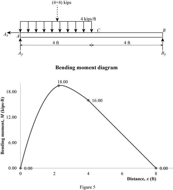
Therefore, the location and magnitude of the maximum absolute bending moment is
(b)
Plot the shear force and bending moment diagram for the beam.
Find the magnitude and location of the maximum absolute value of the bending moment.
(b)
Answer to Problem 7.161RP
The location and magnitude of the maximum absolute bending moment is
Explanation of Solution
Given information:
The moment applied at A is
Calculation:
Show the free-body diagram of the entire beam as in Figure 6.
Find the vertical reaction at point B by taking moment about point A.
Find the vertical reaction at point A by reoslving the vertical component of forces.
Resolve the horizontal component of forces.
Consider the section AC:
Consider a section at a distance x from left end A.
Show the free-body diagram of the section as in Figure 7.
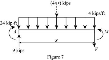
Resolve the vertical component of forces.
Take moment about the section.
At
Substitute 0 for x in Equation (4).
Substitute 0 for x in Equation (5).
At
Substitute 4 ft for x in Equation (4).
Substitute 4 ft for x in Equation (5).
Consider the section CB:
Show the free-body diagram of the section as in Figure 8.
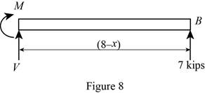
Resolve the vertical component of forces.
Take moment about the section.
At
Substitute 4 ft for x in Equation (6).
At
Substitute 8 ft for x in Equation (6).
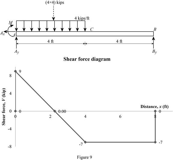
Tabulate the shear force values as in Table 3.
| Location, x ft | Shear force, kips |
| 0 | 9 |
| 4 | –7 |
| 8 | –7 |
Plot the shear force diagram as in Figure 9.
The maximum bending moment occurs where the shear force changes sign.
Refer to the Figure 4, the shear force changes in the section AC.
Substitute 0 for V in Equation (4).
Substitute 2.25 ft for x in Equaiton (5).
Tabulate the bending moment values as in Table 4.
| Location, x ft | Bending moment, kips-ft |
| 0 | 0 |
| 2.25 | 34.125 |
| 4 | 28 |
| 8 | 0 |
Plot the bending moment values as in Figure 10.
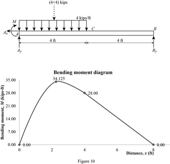
Therefore, the location and magnitude of the maximum absolute bending moment is
Want to see more full solutions like this?
Chapter 7 Solutions
VECTOR MECHANIC


- 2. Jojoba oil is flowing through a ¾-nom stainless steel pipe at a flow rate of 1,850 lbm/h. After the velocity profile in the pipe is fully developed, the oil enters a heater, as shown in Figure P5.7. The length of the heater section is 5 ft. The properties of the jojoba oil at the average temperature in the heater section are given in Table P5.7. Determine the convective heat transfer coefficient inside the heater section of the pipe. ¾ nom stainless steel pipe Heater section L=5ft Fig. P5.7 TABLE P5.7 Thermophysical Properties of Jojoba Oil at the Average Temperature in the Heater P (lbm/ft³) 68.671 (Btu/lbm-R) 0.30339 μ (lbm/ft-s) 0.012095 k (Btu/h-ft-°F) 0.077424arrow_forward1. Water is flowing inside of a 3-std type K copper tube at a flow rate of 1.2 kg/s. The average temperature of the water is 50°C. Cold, dry air at a temperature of 5°C and atmospheric pressure flows outside of the tube in cross flow with a velocity of 85 m/s. Determine the UA product for this tube under clean conditions.arrow_forwardHints: Find the closed loop transfer function and then plot the step response for diFerentvalues of K in MATLAB. Show step response plot for different values of K. Auto Controls Show solutions and provide matlab code NO COPIED ANSWERS OR WILL REPORT!!!!arrow_forward
- 37. The vertical shaft shown in Figure P12-37 is driven at a speed of 600 rpm with 4.0 hp entering through the bevel gear. Each of the two chain sprockets delivers 2.0 hp to the side to drive mixer blades in a chemical reactor vessel. The bevel gear has a diametral pitch of 5, a pitch diameter of 9.000 in, a face width of 1.31 in, and a pressure angle of 20°. Use SAE 4140 OQT 1000 steel for the shaft. See Chapter 10 for the methods for computing the forces on the bevel gear. Figure P12-37: P37-Bevel gear drive with two chain sprockets Each problem includes the following details: ■Design the complete shaft, including the specification of the overall geometry and the consideration of stress con- centration factors. The analysis would show the minimum acceptable diameter at each point on the shaft to be safe from the standpoint of strength. Homework Problems 12-24, 12-35, and 12-37 from textbook, done in spreadsheet form. Place drawings of the load, shear, and bending moment body diagrams…arrow_forward35. The double-reduction, helical gear reducer shown in Figure P12-35 transmits 5.0 hp. Shaft 1 is the input, rotating at 1800 rpm and receiving power directly from an electric motor through a flexible coupling. Shaft 2 rotates at 900 rpm. Shaft 3 is the output, rotating at 300 rpm. A chain sprocket is mounted on the output shaft as shown and delivers the power upward. The data for the gears are given in Table 12-5. Each gear has a 1412° normal pressure angle and a 45° helix angle. The combinations of left- and right-hand helixes are arranged so that the axial forces oppose each other on shaft 2 as shown. Use SAE 4140 OQT 1200 for the shafts. Figure P12-35: P35-Double-reduction helical drive Each problem includes the following details: ■Design the complete shaft, including the specification of the overall geometry and the consideration of stress con- centration factors. The analysis would show the minimum acceptable diameter at each point on the shaft to be safe from the standpoint of…arrow_forwardConsider 0.65 kg of N2 at 300 K, 1 bar contained in a rigid tank connected by a valve to another rigid tank holding 0.3 kg of CO2 at 300 K, 1 bar. The valve is opened and gases are allowed to mix, achieving an equilibrium state at 290 K. Determine: (a) the volume of each tank, in m³. (b) the final pressure, in bar. (c) the magnitude of the heat transfer to or from the gases during the process, in kJ. (d) the entropy change of each gas and of the overall system, in kJ/K.arrow_forward
- Bài 1. Cho cơ hệ như hình 1. Hình biểu diễn lược đổ cơ hệ tại vị trí cân bằng tĩnh. Trục tọa độ Oy hướng theo phương chuyển động của vật 1, gốc O đặt tại vị trí cân bằng của vật 1(tức khi lò xo biến dạng tĩnh). Bỏ qua khối lượng của thanh số 3. Vật rắn 2 là pulley 2 tầng đồng chất có bán kính ngoài 21, bán kính trong I, bán kính quán tính đối với trục qua tâm P-1.5, khối lượng m:. Vật rắn 4 là thanh thắng đồng chất có khối lượng m, chiều dài 1. Cho các số liệu: m = 2kg, m= = 5kg, m = 4kg, k=40(N/cm), ! – 0.8(m),r=0.1(m). Điều kiện đầu y; =0.5 cm );j = 10 cm/s) . Giả sử hệ dao động bé, Vật rắn 2 chuyển động lăn không trượt trên mặt phẳng ngang. 1. Viết phương trình chuyển động của hệ. 2. Xác định tần số dao động tự do của hệ. 3. Xác định đáp ứng dao động tự do của hệ. dây dây 1 2r Hình 1 y 3 -2 I k www. -2arrow_forwardHints: Find the closed loop transfer function and then plot the step response for diFerentvalues of K in MATLAB. Show step response plot for different values of K. Auto Controls Show solutions and provide matlab code NO COPIED ANSWERS OR WILL REPORTarrow_forwardObtain the response of the system shown below for a parabolic or acceleration input r(t);where Auto Controls Show full solutionarrow_forward
- Problem Statement A large plate of insulating material 8 cm thick has in it a 3 cm-diam hole, with axis normal to the surface. The temperature of the surroundings are 1800 K at one side of the plate and 400 K on the other side. Insulating plate D= 3 cm H= 8 cm Considering the sides of the hole to be black, (a) Draw a system of resistors that can be used to solve for the various heat transfer rates. For full credit you must label all "voltages", "currents," and resistances present. (b) Estimate the radiative heat transfer through the hole.arrow_forwardUsing MATLAB, plot the unit-step response curve for the following transfer function and Using MATLAB, obtain the rise time, peak time, maximum overshoot, and settling time. Auto Controls Provide codesarrow_forwardUse Routh's stability criterion to determine how many roots with positive real partsthe following equations have Auto Controls Show full solutionsarrow_forward
 Elements Of ElectromagneticsMechanical EngineeringISBN:9780190698614Author:Sadiku, Matthew N. O.Publisher:Oxford University Press
 Mechanics of Materials (10th Edition)Mechanical EngineeringISBN:9780134319650Author:Russell C. HibbelerPublisher:PEARSON
 Thermodynamics: An Engineering ApproachMechanical EngineeringISBN:9781259822674Author:Yunus A. Cengel Dr., Michael A. BolesPublisher:McGraw-Hill Education
 Control Systems EngineeringMechanical EngineeringISBN:9781118170519Author:Norman S. NisePublisher:WILEY
 Mechanics of Materials (MindTap Course List)Mechanical EngineeringISBN:9781337093347Author:Barry J. Goodno, James M. GerePublisher:Cengage Learning
 Engineering Mechanics: StaticsMechanical EngineeringISBN:9781118807330Author:James L. Meriam, L. G. Kraige, J. N. BoltonPublisher:WILEY