
Fundamentals of Electric Circuits
6th Edition
ISBN: 9780078028229
Author: Charles K Alexander, Matthew Sadiku
Publisher: McGraw-Hill Education
expand_more
expand_more
format_list_bulleted
Concept explainers
Videos
Textbook Question
Chapter 7.2, Problem 1PP
Refer to the circuit in Fig. 7.7. Let vC (0) = 60 V. Determine vC, vx, and io for t ≥ 0.
Answer: 60e−0.25t V, 20e−0.25t V, −5e−0.25t A.
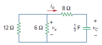
Figure 7.7
For Practice Prob. 7.1.
Expert Solution & Answer
Want to see the full answer?
Check out a sample textbook solution
Students have asked these similar questions
3. Describe the function of PLL circuit.
4. Describe the function of bandpass filter.
ASK Modulator/Demodulator
U1
VD Signal in
VT out
X1
W
R1
VC Carrier in
w
x2
100K
3
Y1
4
Y2 AD633 Z
VR1
10K
VR1
Multiplier(1)
I
U2
Vx out
X1
W
R3
2
w
x2
In2
100K
3
۲۱
I
Y2 AD633
Z
VR2
R2
10K
C4
100K
VR2
Multiplier(2)
+5V
200p
R5
R6
R101K
ww w
2.7K
22K
1N4148
D1
559
VE out
D+
In(ac)
6 0H
200p
HH
6
VLP out
Vo out
U3
VR
0.01
0.1u
R8
VR3
ww
50K
Envelope Detector
10K
U3
LF356
VR3
LPF
U4Σ
LM311
Comparator
U5
PLL in CS
HH
14 SIGN IN
0.1u
6 CIA
PC1OUT 2
PULSES
PHASE(2)
COMPARATOR OUT 13.
C10
HT
150p R16
ww
R12
VSO
C6
200p
VCO OUT 4
IK
in
R14
C9
18K
10 O
w
7 Cle
H
VLO out
6
15K
VCO
150p
06
11 R1
CD4046
VCO IN 9
VR5
1K
12 R2
0.0047u
C7
I
Demod
C8 out
10
SOURCE
FOLLOWER
R11
100K
INH
COMP IN
5
3
VR4
+5V+12V GND-12V
о
HTO
0.1u
R13
10K
I
PL
VR5
Figure 18-10 KL-94005 module
R15
U6Σ
OP37
BPF
DUC
1. Is the waveform on VT out terminal an ASK modulated signal?
TS
PROD
2. Is the waveform on VT out terminal an OOK modulated signal?
ASK Modulator/Demodulator
U1
VD Signal in
VT out
X1
W
R1
VC Carrier in
w
x2
100K
3
Y1
4
Y2 AD633 Z
VR1
10K
VR1
Multiplier(1)
I
U2
Vx out
X1
W
R3
2
w
x2
In2
100K
3
۲۱
I
Y2 AD633
Z
VR2
R2
10K
C4
100K
VR2
Multiplier(2)
+5V
200p
R5
R6
R101K
ww w
2.7K
22K
1N4148
D1
559
VE out
D+
In(ac)
6 0H
200p
HH
6
VLP out
Vo out
U3
VR
0.01
0.1u
R8
VR3
ww
50K
Envelope Detector
10K
U3
LF356
VR3
LPF
U4Σ
LM311
Comparator
U5
PLL in CS
HH
14 SIGN IN
PC1OUT 2
0.1u
6 CIA
PULSES
PHASE(2)
COMPARATOR
OUT 13
C10
HT
150p R16
ww
R12
VSO
18K
C6
200p
VCO OUT 4
IK
in
R14
C9
10 O
w
H
VLO out
6
7 Cle
15K
VCO
150p
06
11 R1
CD4046
VCO IN 9
VR5
1K
12 R2
0.0047u
C7
I
Demod
C8 out
10
SOURCE
FOLLOWER
R11
100K
INH
COMP IN
5
3
VR4
+5V+12V GND-12V
о
HTO
0.1u
R13
10K
I
PL
Figure 18-10 KL-94005 module
VR5
R15
U6Σ
OP37
BPF
h
e
6. Discuss the relationship between Vx out and VLP out signals.
7. Describe the function of comparator.
ASK Modulator/Demodulator
U1
VD Signal in
VT out
X1
W
R1
VC Carrier in
w
x2
100K
3
Y1
4
Y2 AD633 Z
VR1
10K
VR1
Multiplier(1)
I
U2
Vx out
X1
W
R3
2
w
x2
In2
100K
3
۲۱
I
Y2 AD633
Z
VR2
R2
10K
C4
100K
VR2
Multiplier(2)
+5V
200p
R5
R6
R101K
ww w
2.7K
22K
1N4148
D1
559
VE out
D+
In(ac)
6 0H
200p
HH
6
VLP out
Vo out
U3
VR
0.01
0.1u
R8
VR3
ww
50K
Envelope Detector
10K
U3
LF356
VR3
LPF
U4Σ
LM311
Comparator
U5
PLL in CS
HH
14 SIGN IN
0.1u
6 CIA
PC1OUT 2
PULSES
PHASE(2)
COMPARATOR OUT 13.
C10
HT
150p R16
ww
R12
VSO
C6
200p
VCO OUT 4
IK
in
R14
C9
18K
10 O
w
7 Cle
H
VLO out
6
15K
VCO
150p
06
11 R1
CD4046
VCO IN 9
VR5
1K
12 R2
0.0047u
C7
I
Demod
C8 out
10
SOURCE
FOLLOWER
R11
100K
INH
COMP IN
5
3
VR4
+5V+12V GND-12V
о
HTO
0.1u
R13
10K
I
PL
VR5
Figure 18-10 KL-94005 module
R15
U6Σ
OP37
BPF
Chapter 7 Solutions
Fundamentals of Electric Circuits
Ch. 7.2 - Refer to the circuit in Fig. 7.7. Let vC (0) = 60...Ch. 7.2 - If the switch in Fig. 7.10 opens at t = 0, find...Ch. 7.3 - Find i and vx in the circuit of Fig. 7.15. Let...Ch. 7.3 - For the circuit in Fig. 7.18, find i(t) for t 0....Ch. 7.3 - Determine i, io, and vo for all t in the circuit...Ch. 7.4 - Express the current pulse in Fig. 7.33 in terms of...Ch. 7.4 - Refer to Fig. 7.39. Express i(t) in terms of...Ch. 7.4 - If h t = 0, t0 4, 0t2 3t8, 2t6 0, t6 express h(t)...Ch. 7.4 - Practice Problem 7.9 Evaluate the following...Ch. 7.5 - Find v(t) for t 0 in the circuit of Fig. 7.44....
Ch. 7.5 - The switch in Fig. 7.47 is closed at t = 0. Find...Ch. 7.6 - The switch in Fig. 7.52 has been closed for a long...Ch. 7.6 - Switch S1 in Fig. 7.54 is closed at t = 0, and...Ch. 7.7 - For the op amp circuit in Fig. 7.56, find vo for t...Ch. 7.7 - Find v(t) and vo(t) in the op amp circuit of Fig....Ch. 7.7 - Obtain the step response vo(t) for the circuit in...Ch. 7.8 - For the circuit in Fig. 7.66, use Pspice to find...Ch. 7.8 - The switch in Fig. 7.71 was open for a long time...Ch. 7.9 - The RC circuit in Fig. 7.74 is designed to operate...Ch. 7.9 - The flash unit of a camera has a 2-mF capacitor...Ch. 7.9 - A relay has a resistance of 200 and an inductance...Ch. 7.9 - Prob. 22PPCh. 7 - An RC circuit has R = 2 and C = 4 F. The time...Ch. 7 - The time constant for an RL circuit with R = 2 ...Ch. 7 - A capacitor in an RC circuit with R = 2 and C = 4...Ch. 7 - An RL circuit has R = 2 and L = 4 H. The time...Ch. 7 - In the circuit of Fig. 7.79, the capacitor voltage...Ch. 7 - Figure 7.79 For Review Questions 7.5 and 7.6....Ch. 7 - For the circuit in Fig. 7.80, the inductor current...Ch. 7 - Figure 7.80 For Review Questions 7.7 and 7.8....Ch. 7 - If vs changes from 2 V to 4 V at t = 0, we may...Ch. 7 - The pulse in Fig. 7.116(a) can be expressed in...Ch. 7 - In the circuit shown in Fig. 7.81...Ch. 7 - Find the time constant for the RC circuit in Fig....Ch. 7 - Determine the time constant for the circuit in...Ch. 7 - The switch in Fig. 7.84 has been in position A for...Ch. 7 - Using Fig. 7.85, design a problem to help other...Ch. 7 - The switch in Fig. 7.86 has been closed for a long...Ch. 7 - Assuming that the switch in Fig. 7.87 has been in...Ch. 7 - For the circuit in Fig. 7.88, if...Ch. 7 - The switch in Fig. 7.89 opens at t = 0. Find vo...Ch. 7 - For the circuit in Fig. 7.90, find vo(t) for t 0....Ch. 7 - For the circuit in Fig. 7.91, find io for t 0....Ch. 7 - Using Fig. 7.92, design a problem to help other...Ch. 7 - In the circuit of Fig. 7.93,...Ch. 7 - Calculate the time constant of the circuit in Fig....Ch. 7 - Find the time constant for each of the circuits in...Ch. 7 - Determine the time constant for each of the...Ch. 7 - Consider the circuit of Fig. 7.97. Find vo(t) if...Ch. 7 - For the circuit in Fig. 7.98, determine vo(t) when...Ch. 7 - In the circuit of Fig. 7.99, find i(t) for t 0 if...Ch. 7 - For the circuit in Fig. 7.100, v = 90e50t V and i...Ch. 7 - In the circuit of Fig. 7.101, find the value of R...Ch. 7 - Find i(t) and v(t) for t 0 in the circuit of Fig....Ch. 7 - Consider the circuit in Fig. 7.103. Given that...Ch. 7 - Express the following signals in terms of...Ch. 7 - Design a problem to help other students better...Ch. 7 - Express the signals in Fig. 7.104 in terms of...Ch. 7 - Express v(t) in Fig. 7.105 in terms of step...Ch. 7 - Sketch the waveform represented by i(t) = [r(t) ...Ch. 7 - Sketch the following functions: (a) x(t) = 10etu(t...Ch. 7 - Prob. 30PCh. 7 - Evaluate the following integrals: (a)e4t2(t2)dt...Ch. 7 - Prob. 32PCh. 7 - The voltage across a 10-mH inductor is 45(t 2)mV....Ch. 7 - Evaluate the following derivatives: (a) ddtut1ut+1...Ch. 7 - Find the solution to the following differential...Ch. 7 - Solve for v in the following differential...Ch. 7 - A circuit is described by 4dvdt+v=10 (a) What is...Ch. 7 - A circuit is described by didt+3i=2ut Find i(t)...Ch. 7 - Calculate the capacitor voltage for t 0 and t 0...Ch. 7 - Find the capacitor voltage for t 0 and t 0 for...Ch. 7 - Using Fig. 7.108, design a problem to help other...Ch. 7 - (a) If the switch in Fig. 7.109 has been open for...Ch. 7 - Consider the circuit in Fig. 7.110. Find i(t) for...Ch. 7 - The switch in Fig. 7.111 has been in position a...Ch. 7 - Find vo in the circuit of Fig. 7.112 when vs =...Ch. 7 - Prob. 46PCh. 7 - Determine v(t) for t 0 in the circuit of Fig....Ch. 7 - Find v(t) and i(t) in the circuit of Fig. 7.115....Ch. 7 - If the waveform in Fig. 7.116(a) is applied to the...Ch. 7 - In the circuit of Fig. 7.117, find ix for t 0....Ch. 7 - Rather than applying the shortcut technique used...Ch. 7 - Using Fig. 7.118, design a problem to help other...Ch. 7 - Determine the inductor current i(t) for both t 0...Ch. 7 - Obtain the inductor current for both t 0 and t 0...Ch. 7 - Find v(t) for t 0 and t 0 in the circuit of Fig....Ch. 7 - Prob. 56PCh. 7 - Prob. 57PCh. 7 - Rework Prob. 7.17 if i(0) = 10 A and v(t) = 20u(t)...Ch. 7 - Determine the step response vo(t) to is = 6u(t) A...Ch. 7 - Find v(t) for t 0 in the circuit of Fig. 7.125 if...Ch. 7 - In the circuit in Fig. 7.126, is changes from 5 A...Ch. 7 - For the circuit in Fig. 7.127, calculate i(t) if...Ch. 7 - Obtain v(t) and i(t) in the circuit of Fig. 7.128....Ch. 7 - Determine the value of iL(t) and the total energy...Ch. 7 - If the input pulse in Fig. 7.130(a) is applied to...Ch. 7 - Using Fig. 7.131, design a problem to help other...Ch. 7 - If v(0) = 10 V, find vo(t) for t 0 in the op amp...Ch. 7 - Prob. 68PCh. 7 - For the op amp circuit in Fig. 7.134, find vo(t)...Ch. 7 - Determine vo for t 0 when vs = 20 mV in the op...Ch. 7 - For the op amp circuit in Fig. 7.136, suppose vs =...Ch. 7 - Find io in the op amp circuit in Fig. 7.137....Ch. 7 - For the op amp circuit of Fig. 7.138, let R1 = 10...Ch. 7 - Determine vo(t) for t 0 in the circuit of Fig....Ch. 7 - In the circuit of Fig. 7.140, find vo and io,...Ch. 7 - Repeat Prob. 7.49 using PSpice or MultiSim. If the...Ch. 7 - The switch in Fig. 7.141 opens at t = 0. Use...Ch. 7 - The switch in Fig. 7.142 moves from position a to...Ch. 7 - In the circuit of Fig. 7.143, determine io(t)....Ch. 7 - In the circuit of Fig. 7.144, find the value of io...Ch. 7 - Repeat Prob. 7.65 using PSpice or MultiSim. If the...Ch. 7 - In designing a signal-switching circuit, it was...Ch. 7 - Prob. 83PCh. 7 - A capacitor with a value of 10 mF has a leakage...Ch. 7 - A simple relaxation oscillator circuit is shown in...Ch. 7 - Figure 7.146 shows a circuit for setting the...Ch. 7 - A 120-V dc generator energizes a motor whose coil...Ch. 7 - The circuit in Fig. 7.148(a) can be designed as an...Ch. 7 - An RL circuit may be used as a differentiator if...Ch. 7 - An attenuator probe employed with oscilloscopes...Ch. 7 - The circuit in Fig. 7.150 is used by a biology...Ch. 7 - To move a spot of a cathode-ray tube across the...
Additional Engineering Textbook Solutions
Find more solutions based on key concepts
How are relationships between tables expressed in a relational database?
Modern Database Management
17–1C A high-speed aircraft is cruising in still air. How does the temperature of air at the nose of the aircra...
Thermodynamics: An Engineering Approach
Assume a telephone signal travels through a cable at two-thirds the speed of light. How long does it take the s...
Electric Circuits. (11th Edition)
What types of coolant are used in vehicles?
Automotive Technology: Principles, Diagnosis, And Service (6th Edition) (halderman Automotive Series)
The solid steel shaft AC has a diameter of 25 mm and is supported by smooth bearings at D and E. It is coupled ...
Mechanics of Materials (10th Edition)
What is an uninitialized variable?
Starting Out with Programming Logic and Design (5th Edition) (What's New in Computer Science)
Knowledge Booster


Learn more about
Need a deep-dive on the concept behind this application? Look no further. Learn more about this topic, electrical-engineering and related others by exploring similar questions and additional content below.Similar questions
- Choose one of the choices indicated in the parentheses such as the following sentences have correct messing What is the main purpose of a communication system? a) To transmit information from one point to another b) To amplify signals for better reception c) To filter out unwanted noise dy To generate carrier waves for modulation 2. What the purpose of the modulator in a communication system? a) To generate the cares wave for modulation b) To convert the information signal to a modulated signal c) To filter out unwanted noise d) To amplify the modulated signal for transmission Which component in an FM transmitter is responsible for generating the carrier signal? a) Mixer b) Modulator c) Demodulator d) Oscillator 4 For a FM signal v(t) 25 cos (15 deviation 10 (3456 4 24669, 7321 7.21284) 117 10 sm 15501). Maximum frequency 5. In an AM receiver, which component is responsible for separating the modulating signal from the received AM signal? a) Mixer b) Modulator c) Demodulator dy…arrow_forwardQ1. Choose the correct answer: 1. Increasing the amplitude of a square pulse (increases, decreases, maintains not related) the spectrum range in the frequency domain. 2. A continuous FT indicates a signal. (continuous, discrete, periodic non-periodic). the pulse duration is proportional to the amplitude of the signal. (PAM, PWM, PPM, 3. In ASK). . In VSB transmission (both sidebands are used, single sideband is used, single sideband and part of the other sideband, only the vestige of the carrier signal is used). 5. An economic FDM receiver design should contain simultaneous reception, selective reception). 6. In AMI code, the shapes of "1" and "0" are dependent, not related to each other). 7. In FDM the guard band is used to (pilot carrier zero crossing detector, (the same) opposite to each other, next bit increase the overlap between FDM signals, decrease the overlap between FDM signals, increase the baseband bandwidth, decrease the baseband bandwidth). 20 3. Higher number of levels…arrow_forwardIn a railway system with a power source of 600 VDC, I need to achieve a load output of 120 VDC for railway lights. I found a DC-DC converter capable of stepping down 600 VDC to 125 VDC. To obtain 120 VDC from this converter, we can use a voltage divider with the following equation: [R2/(R2+R1)]=120/125=0.96=0.96However, using resistors to achieve the desired output voltage raises some concerns. Is it advisable to use railway-grade resistors for this application? I found some resistors in the range of 1-10k ohms, but I am unsure how they should be connected in the circuit with the lights (the load to be used). I would greatly appreciate any suggestions or schematic diagrams to clarify the best approach for connecting the resistors in this setup.arrow_forward
- Find the valve of the voltage Vx using the THEVENIN equivalent circuit and redo the problem with the NORTON equivalent circuit. Show both the the vinen and Norton circuits. I 12V m 1 ww 3 23 + 43Vx 5 63 миarrow_forwardFind the valve of V using the Thevenin Equivalent Circuit and then determine if the 8 ohm resistor allows maximum power transfer. If not, then what value should the 8 ohm resistor be changed to for maximum power transfer? ZA 6 6 + 22V 83 V 34 2 6 АААА ААААarrow_forwardFind the valve of voltage Vx using the THE VIN IN equivalent circuit ww 8 Show the Theven in Circuit. I 7V ZV m 6 5 M + 4 34 АА 3 1 АААА 9A ↑ 24arrow_forward
arrow_back_ios
SEE MORE QUESTIONS
arrow_forward_ios
Recommended textbooks for you
 Introductory Circuit Analysis (13th Edition)Electrical EngineeringISBN:9780133923605Author:Robert L. BoylestadPublisher:PEARSON
 Delmar's Standard Textbook Of ElectricityElectrical EngineeringISBN:9781337900348Author:Stephen L. HermanPublisher:Cengage Learning
 Programmable Logic ControllersElectrical EngineeringISBN:9780073373843Author:Frank D. PetruzellaPublisher:McGraw-Hill Education
 Fundamentals of Electric CircuitsElectrical EngineeringISBN:9780078028229Author:Charles K Alexander, Matthew SadikuPublisher:McGraw-Hill Education
 Electric Circuits. (11th Edition)Electrical EngineeringISBN:9780134746968Author:James W. Nilsson, Susan RiedelPublisher:PEARSON
 Engineering ElectromagneticsElectrical EngineeringISBN:9780078028151Author:Hayt, William H. (william Hart), Jr, BUCK, John A.Publisher:Mcgraw-hill Education,
Introductory Circuit Analysis (13th Edition)
Electrical Engineering
ISBN:9780133923605
Author:Robert L. Boylestad
Publisher:PEARSON
Delmar's Standard Textbook Of Electricity
Electrical Engineering
ISBN:9781337900348
Author:Stephen L. Herman
Publisher:Cengage Learning
Programmable Logic Controllers
Electrical Engineering
ISBN:9780073373843
Author:Frank D. Petruzella
Publisher:McGraw-Hill Education
Fundamentals of Electric Circuits
Electrical Engineering
ISBN:9780078028229
Author:Charles K Alexander, Matthew Sadiku
Publisher:McGraw-Hill Education
Electric Circuits. (11th Edition)
Electrical Engineering
ISBN:9780134746968
Author:James W. Nilsson, Susan Riedel
Publisher:PEARSON
Engineering Electromagnetics
Electrical Engineering
ISBN:9780078028151
Author:Hayt, William H. (william Hart), Jr, BUCK, John A.
Publisher:Mcgraw-hill Education,
ENA 9.2(1)(En)(Alex) Sinusoids & Phasors - Explanation with Example 9.1 ,9.2 & PP 9.2; Author: Electrical Engineering Academy;https://www.youtube.com/watch?v=vX_LLNl-ZpU;License: Standard YouTube License, CC-BY
Electrical Engineering: Ch 10 Alternating Voltages & Phasors (8 of 82) What is a Phasor?; Author: Michel van Biezen;https://www.youtube.com/watch?v=2I1tF3ixNg0;License: Standard Youtube License