
Concept explainers
Videos
(a)
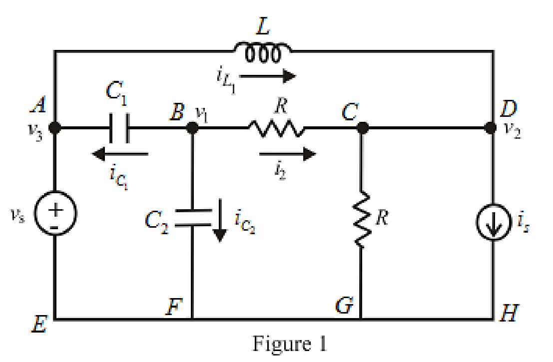
Write the nodal equation of the circuit.
(a)
Answer to Problem 45E
The nodal equation of the circuit at node voltage
Explanation of Solution
Calculation:
The redrawn circuit is shown in Figure 1.
Here,
The expression for the current across the inductor is,
Here,
The expression for the current across capacitor is,
Here,
The expression for the nodal analysis at node
Rearrange equation (3),
The voltage at node voltage
Substitute
The expression for the nodal analysis at node voltage
The node voltage across resistance
Rearrange equation (7),
Conclusion:
Thus, the nodal equation of the circuit at node voltage
(b)
Write the mesh equation of the circuit.
(b)
Answer to Problem 45E
The mesh equation of the circuit in loop
Explanation of Solution
Calculation:
The redrawn circuit is shown in Figure 2 as follows,
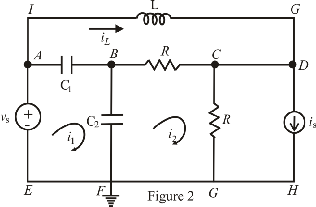
Refer to the Figure 2,
The voltage at node voltage
The expression for mesh equation in loop
Here,
Substitute
The expression for mesh equation in loop
Substitute
The expression for mesh equation in loop
Conclusion:
Thus, the mesh equation of the circuit in loop
Want to see more full solutions like this?
Chapter 7 Solutions
Engineering Circuit Analysis


- I need help fixing this MATLAB code: as I try to get it working there were some problems:arrow_forwardI need help in construct a matlab code to find the voltage of VR1 to VR4, the currents, and the watts based on that circuit.arrow_forwardQ2: Using D flip-flops, design a synchronous counter. The counter counts in the sequence 1,3,5,7, 1,7,5,3,1,3,5,7,.... when its enable input x is equal to 1; otherwise, the counter count 0.arrow_forward
- From the collector characteristic curves and the dc load line given below, determine the following: (a) Maximum collector current for linear operation (b) Base current at the maximum collector current (c) VCE at maximum collector current. lc (mA) 600 ΜΑ 60- 500 με 50- 400 με 40- 300 μ Α 30- Q-point 200 ΜΑ 20- 10- 100 μ Α 0 VCE (V) 1 2 3 4 5 6 7 8 9 10 [6 Paarrow_forwardProcedure:- 1- Connect the cct. shown in fig.(2). a ADDS DS Fig.(2) 2-For resistive load, measure le output voltage by using oscilloscope ;then sketch this wave. 3- Measure the average values ::f VL and IL: 4- Repeat steps 2 & 3 but for RL load. Report:- 1- Calculate the D.C. output vcl age theoretically and compare it with the test value. 2- Calculate the harmonic cont :nts of the load voltage, and explain how filter components may be selected. 3- Compare between the three-phase half & full-wave uncontrolled bridge rectifier. 4- Draw the waveform for the c:t. shown in fig.(2) but after replaced Di and D3 by thyristors with a 30° and a2 = 90° 5- Draw the waveform for the cct. shown in fig.(2) but after replace the 6-diodes by 6- thyristor. 6- Discuss your results. Please solve No. 4 and 5arrow_forwardPlease I want solution by handwrittenarrow_forward
- 8 00 ! Required information Consider the circuit given below. 0/2 points awarded 3 ΚΩ www t=0 6kM Scored R 1.5i Vc 1 μF 10 V If R = 5.00 kQ, determine vao+). The value of va(0) is 1.4545 V.arrow_forwardI want to know what does it look in a breadboard circuit, because I want to created it but I not sure it is build properly, can you give me an illustuation base on this image, it do need to real, something like virutal examplearrow_forwardCharge neutrality Since doped semiconductor remains electroneutral, the concentration of negative charges equals the concentration of positive charges. n+ Na,ionized p+Nd,ionized np = n; 2 2 N-Na N N d d р + 2 2 n = Nd-Na 2 + Na - 2 Na +n₁ 2 71/2 1/2 2 2 +n Concentration of electrons and holes 1. Calculate concentrations of electrons and holes at room temperature in Si and Ge with donor concentration of 1.5x10¹7 cm³ and acceptor concentration of 8x1016 cm-3. 2. Will these concentrations change much with the temperature increase to 100°C?arrow_forward
- Answer the questions on the end of the image pleasearrow_forwardAnswer these two questions on the end of the image, please 1.Calculate intrinsic carrier concentration for Si, Ge and GaAs at temperatures -20°C, 20°C (room temperature) and 120°C 2.Compare the obtained data with n and p shown on previous slide 25arrow_forwardCan you help me achieve the requirements using Arduino? I have encountered some issues with these requirements. Q.2: Suppose you have two push buttons connected to ports (0 & 1) and four LED's connected to ports (6-9). Write a program to flash ON the odd LED's if we press the switch 0 for 4s, flash ON the even LED's if we press the switch 1 for 5s and flash ON all the LED's otherwise for 6s.arrow_forward
 Introductory Circuit Analysis (13th Edition)Electrical EngineeringISBN:9780133923605Author:Robert L. BoylestadPublisher:PEARSON
 Delmar's Standard Textbook Of ElectricityElectrical EngineeringISBN:9781337900348Author:Stephen L. HermanPublisher:Cengage Learning
 Programmable Logic ControllersElectrical EngineeringISBN:9780073373843Author:Frank D. PetruzellaPublisher:McGraw-Hill Education
 Fundamentals of Electric CircuitsElectrical EngineeringISBN:9780078028229Author:Charles K Alexander, Matthew SadikuPublisher:McGraw-Hill Education
 Electric Circuits. (11th Edition)Electrical EngineeringISBN:9780134746968Author:James W. Nilsson, Susan RiedelPublisher:PEARSON
 Engineering ElectromagneticsElectrical EngineeringISBN:9780078028151Author:Hayt, William H. (william Hart), Jr, BUCK, John A.Publisher:Mcgraw-hill Education,