
Engineering Circuit Analysis
9th Edition
ISBN: 9780073545516
Author: Hayt, William H. (william Hart), Jr, Kemmerly, Jack E. (jack Ellsworth), Durbin, Steven M.
Publisher: Mcgraw-hill Education,
expand_more
expand_more
format_list_bulleted
Concept explainers
Videos
Textbook Question
Chapter 7, Problem 37E
Reduce the circuit depicted in Fig. 7.59 to as few components as possible, noting that the voltage vx is important.
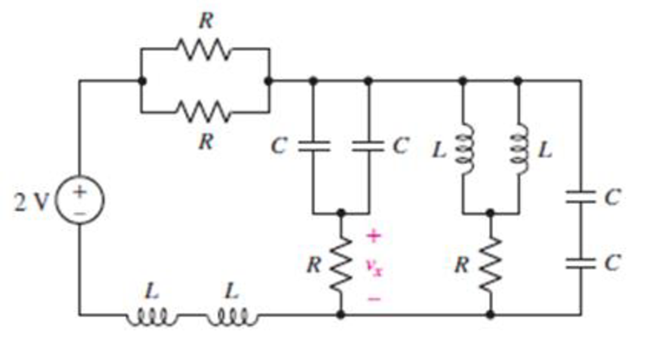
FIGURE 7.59
Expert Solution & Answer
Want to see the full answer?
Check out a sample textbook solution
Students have asked these similar questions
I need help checking if its correct
-E1 + VR1 + VR4 – E2 + VR3 = 0 -------> Loop 1 (a)
R1(I1) + R4(I1 – I2) + R3(I1) = E1 + E2 ------> Loop 1 (b)
R1(I1) + R4(I1) - R4(I2) + R3(I1) = E1 + E2 ------> Loop 1 (c)
(R1 + R3 + R4) (I1) - R4(I2) = E1 + E2 ------> Loop 1 (d)
Now that we have loop 1 equation will procced on finding the equation of I2 current loop. However, a reminder that because we are going in a clockwise direction, it goes against the direction of the current. As such we will get an equation for the matrix that will be:
E2 – VR4 – VR2 + E3 = 0 ------> Loop 2 (a)
-R4(I2 – I1) -R2(I2) = -E2 – E3 ------> Loop 2 (b)
-R4(I2) + R4(I1) - R2(I2) = -E2 – E3 -----> Loop 2 (c)
R4(I1) – (R4 + R2)(I2) = -E2 – E3 -----> Loop 2 (d)
These two equations will be implemented to the matrix formula I = inv(A) * b
R11 R12
(R1 + R3 + R4)
-R4
-R4
R4 + R2
10.2 For each of the following groups of sources, determineif the three sources constitute a balanced source, and if it is,determine if it has a positive or negative phase sequence.(a) va(t) = 169.7cos(377t +15◦) Vvb(t) = 169.7cos(377t −105◦) Vvc(t) = 169.7sin(377t −135◦) V(b) va(t) = 311cos(wt −12◦) Vvb(t) = 311cos(wt +108◦) Vvc(t) = 311cos(wt +228◦) V(c) V1 = 140 −140◦ VV2 = 114 −20◦ VV3 = 124 100◦ V
Apply single-phase equivalency to determine the linecurrents in the Y-D network shown in Fig. P10.13. The loadimpedances are Zab = Zbc = Zca = (25+ j5) W
Chapter 7 Solutions
Engineering Circuit Analysis
Ch. 7.1 - Determine the current flowing through a 5 mF...Ch. 7.1 - Prob. 2PCh. 7.1 - Prob. 3PCh. 7.2 - 7.4 The current through a 200 mH inductor is shown...Ch. 7.2 - The current waveform of Fig. 7.14a has equal rise...Ch. 7.2 - Prob. 6PCh. 7.2 - Let L = 25 mH for the inductor of Fig. 7.10. (a)...Ch. 7.3 - Find Ceq for the network of Fig. 7.23. FIGURE...Ch. 7.4 - If vC(t) = 4 cos 105t V in the circuit in Fig....Ch. 7.5 - Derive an expression for vout in terms of vs for...
Ch. 7.6 - Prob. 11PCh. 7 - Making use of the passive sign convention,...Ch. 7 - Prob. 2ECh. 7 - (a) If the voltage waveform depicted in Fig. 7.42...Ch. 7 - A capacitor is constructed from two brass plates,...Ch. 7 - Prob. 5ECh. 7 - Prob. 6ECh. 7 - Design a capacitor whose capacitance can be varied...Ch. 7 - Design a capacitor whose capacitance can be varied...Ch. 7 - Prob. 9ECh. 7 - Assuming the passive sign convention, sketch the...Ch. 7 - Prob. 11ECh. 7 - Prob. 12ECh. 7 - Prob. 13ECh. 7 - Calculate the power dissipated in the 40 resistor...Ch. 7 - Prob. 15ECh. 7 - Design a 30 nH inductor using 28 AWG solid soft...Ch. 7 - Prob. 17ECh. 7 - Prob. 18ECh. 7 - Prob. 19ECh. 7 - Prob. 20ECh. 7 - Calculate vL and iL for each of the circuits...Ch. 7 - The current waveform shown in Fig. 7.14 has a rise...Ch. 7 - Determine the inductor voltage which results from...Ch. 7 - Prob. 24ECh. 7 - The voltage across a 2 H inductor is given by vL =...Ch. 7 - Calculate the energy stored in a 1 nH inductor if...Ch. 7 - Determine the amount of energy stored in a 33 mH...Ch. 7 - Making the assumption that the circuits in Fig....Ch. 7 - Calculate the voltage labeled vx in Fig. 7.52,...Ch. 7 - Prob. 30ECh. 7 - Prob. 31ECh. 7 - Determine an equivalent inductance for the network...Ch. 7 - Using as many 1 nH inductors as you like, design...Ch. 7 - Compute the equivalent capacitance Ceq as labeled...Ch. 7 - Prob. 35ECh. 7 - Prob. 36ECh. 7 - Reduce the circuit depicted in Fig. 7.59 to as few...Ch. 7 - Refer to the network shown in Fig. 7.60 and find...Ch. 7 - Prob. 39ECh. 7 - Prob. 40ECh. 7 - Prob. 41ECh. 7 - Prob. 42ECh. 7 - Prob. 43ECh. 7 - Prob. 44ECh. 7 - Prob. 45ECh. 7 - Prob. 46ECh. 7 - Prob. 47ECh. 7 - Let vs = 100e80t V with no initial energy stored...Ch. 7 - Prob. 49ECh. 7 - Prob. 50ECh. 7 - Interchange the location of R1 and Cf in the...Ch. 7 - For the integrating amplifier circuit of Fig....Ch. 7 - Prob. 53ECh. 7 - For the circuit shown in Fig. 7.73, assume no...Ch. 7 - A new piece of equipment designed to make crystals...Ch. 7 - An altitude sensor on a weather balloon provides a...Ch. 7 - One problem satellites face is exposure to...Ch. 7 - The output of a velocity sensor attached to a...Ch. 7 - A floating sensor in a certain fuel tank is...Ch. 7 - (a) If Is = 3 sin t A, draw the exact dual of the...Ch. 7 - Draw the exact dual of the simple circuit shown in...Ch. 7 - (a) Draw the exact dual of the simple circuit...Ch. 7 - (a) Draw the exact dual of the simple circuit...Ch. 7 - Prob. 64ECh. 7 - Prob. 65ECh. 7 - Prob. 66ECh. 7 - Prob. 67ECh. 7 - Prob. 68ECh. 7 - Prob. 69ECh. 7 - Prob. 70ECh. 7 - For the circuit of Fig. 7.28, (a) sketch vout over...Ch. 7 - (a) Sketch the output function vout of the...Ch. 7 - For the circuit of Fig. 7.72, (a) sketch vout over...
Knowledge Booster


Learn more about
Need a deep-dive on the concept behind this application? Look no further. Learn more about this topic, electrical-engineering and related others by exploring similar questions and additional content below.Similar questions
- 10.8 In the network of Fig. P10.8, Za = Zb = Zc = (25+ j5) W.Determine the line currents.arrow_forwardUsing D flip-flops, design a synchronous counter. The counter counts in the sequence 1,3,5,7, 1,7,5,3,1,3,5,7,.... when its enable input x is equal to 1; otherwise, the counter count 0. Present state Next state x=0 Next state x=1 Output SO 52 S1 1 S1 54 53 3 52 53 S2 56 51 0 $5 5 54 S4 53 0 55 58 57 7 56 56 55 0 57 S10 59 1 58 58 S7 0 59 S12 S11 7 $10 $10 59 0 $11 $14 $13 5 $12 S12 $11 0 513 $15 SO 3 S14 $14 S13 0 $15 515 SO 0 Explain how to get the table step by step with drawing the state diagram and finding the Karnaugh map.arrow_forwardFor the oscillator resonance circuit shown in Fig. (5), derive the oscillation frequency Feedback and open-loop gains. L₁ 5 mH (a) ell +10 V R₁ ww R3 S C2 HH 1 με 1000 pF 100 pF R₂ 1 με RA H (b) +9 V R4 CA 470 pF C₁ R3 HH 1 με R₁ ww L₁ 000 1.5 mH R₂ ww Hi 1 μF L2 m 10 mHarrow_forward
- Expert handwritten solution onlyarrow_forwardB. For the oscillator circuit shown in frequency, feedback and open-loop gains. +10 V name the circuit, derive and find the oscillation P.Av +9 V -000 4₁ 5 mH w R₁ C₂ HH 1 με w 100 pF R₂ T R CA www. 470 pF w ww www 1000 pF HH 1μF C₁ HH 1μF Ra ww HI 4₁ 000 1.5 mH H 4 AF 000 10 mHarrow_forwardI want to check if the current that I have from using the mesh analysis is correct? I1 = 0.214mA I2 = -0.429mAarrow_forward
- I want to find the current by using mesh analysis pleasearrow_forwardI want to find the current by using mesh analysis pleasearrow_forwardR₁ W +10 V R3 +9 V C₂ R₁ CA C₁ 470 pF HH 1000 pF HH 1 με C4 1 μF 1 uF C₁ R₂ R4 100 pF Find Open-loop Jain L₁ 5 mH (a) Av=S,B={" H R₁₂ ✓ ww (b) R₁ L₁ 000 1.5 mH R₂ H 1 uF 12 10 mHarrow_forward
- A) Calculate the efficiency of the test transformer at the resistive loads (X-25%, 50%, 75%, 100%, 125% full load). B) From part (A) draw the plot (efficiency Vs power output) of the transformer. C) Discuss the plot of part (B).arrow_forwarda- Determine fH; and Ho b- Find fg and fr. c- Sketch the frequency response for the high-frequency region using a Bode plot and determine the cutoff frequency. Ans: 277.89 KHz; 2.73 MHz; 895.56 KHz; 107.47 MHz. 14V Cw=5pF Cwo-8pF Coc-12 pF 5.6kQ Ch. 40. pF C-8pF 68kQ 0.47µF Vo 0.82 kQ V₁ B=120 0.47µF www 3.3kQ 10kQ 1.2kQ =20µF Narrow_forwardUsing D flip-flops, design a synchronous counter. The counter counts in the sequence 1,3,5,7, 1,7,5,3,1,3,5,7,.... when its enable input x is equal to 1; otherwise, the counter. This counter is for individual settings only need the state diagram and need the state table to use 16 states from So to S15.arrow_forward
arrow_back_ios
SEE MORE QUESTIONS
arrow_forward_ios
Recommended textbooks for you
 Introductory Circuit Analysis (13th Edition)Electrical EngineeringISBN:9780133923605Author:Robert L. BoylestadPublisher:PEARSON
 Delmar's Standard Textbook Of ElectricityElectrical EngineeringISBN:9781337900348Author:Stephen L. HermanPublisher:Cengage Learning
 Programmable Logic ControllersElectrical EngineeringISBN:9780073373843Author:Frank D. PetruzellaPublisher:McGraw-Hill Education
 Fundamentals of Electric CircuitsElectrical EngineeringISBN:9780078028229Author:Charles K Alexander, Matthew SadikuPublisher:McGraw-Hill Education
 Electric Circuits. (11th Edition)Electrical EngineeringISBN:9780134746968Author:James W. Nilsson, Susan RiedelPublisher:PEARSON
 Engineering ElectromagneticsElectrical EngineeringISBN:9780078028151Author:Hayt, William H. (william Hart), Jr, BUCK, John A.Publisher:Mcgraw-hill Education,
Introductory Circuit Analysis (13th Edition)
Electrical Engineering
ISBN:9780133923605
Author:Robert L. Boylestad
Publisher:PEARSON
Delmar's Standard Textbook Of Electricity
Electrical Engineering
ISBN:9781337900348
Author:Stephen L. Herman
Publisher:Cengage Learning
Programmable Logic Controllers
Electrical Engineering
ISBN:9780073373843
Author:Frank D. Petruzella
Publisher:McGraw-Hill Education
Fundamentals of Electric Circuits
Electrical Engineering
ISBN:9780078028229
Author:Charles K Alexander, Matthew Sadiku
Publisher:McGraw-Hill Education
Electric Circuits. (11th Edition)
Electrical Engineering
ISBN:9780134746968
Author:James W. Nilsson, Susan Riedel
Publisher:PEARSON
Engineering Electromagnetics
Electrical Engineering
ISBN:9780078028151
Author:Hayt, William H. (william Hart), Jr, BUCK, John A.
Publisher:Mcgraw-hill Education,
ENA 9.2(1)(En)(Alex) Sinusoids & Phasors - Explanation with Example 9.1 ,9.2 & PP 9.2; Author: Electrical Engineering Academy;https://www.youtube.com/watch?v=vX_LLNl-ZpU;License: Standard YouTube License, CC-BY
Electrical Engineering: Ch 10 Alternating Voltages & Phasors (8 of 82) What is a Phasor?; Author: Michel van Biezen;https://www.youtube.com/watch?v=2I1tF3ixNg0;License: Standard Youtube License