Concept explainers
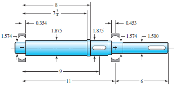
In the figure is a proposed shaft design to be used for the input shaft a in Prob. 7–17. A ball bearing is planned for the left bearing, and a cylindrical roller bearing for the right.
(a) Determine the minimum fatigue factor of safety by evaluating at any critical locations. Use the DE-ASME Elliptic fatigue criterion.
(b) Check the design for adequacy with respect to deformation, according to the recommendations in Table 7–2.

Problem 7–18
Shoulder fillets at bearing seat 0.030-in radius, others
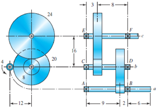
In the double-reduction gear train shown, shaft a is driven by a motor attached by a flexible coupling attached to the overhang. The motor provides a torque of 2500 lbf · in at a speed of 1200 rpm. The gears have 20° pressure angles, with diameters shown in the figure. Use an AISI 1020 cold-drawn steel. Design one of the shafts (as specified by the instructor) with a design factor of 1.5 by performing the following tasks.
(a) Sketch a general shaft layout, including means to locate the gears and bearings, and to transmit the torque.
(b) Perform a force analysis to find the bearing reaction forces, and generate shear and bending moment diagrams.
(c) Determine potential critical locations for stress design.
(d) Determine critical diameters of the shaft based on fatigue and static stresses at the critical locations.
(e) Make any other dimensional decisions necessary to specify all diameters and axial dimensions. Sketch the shaft to scale, showing all proposed dimensions.
(f) Check the deflection at the gear, and the slopes at the gear and the bearings for satisfaction of the recommended limits in Table 7–2.
(g) If any of the deflections exceed the recommended limits, make appropriate changes to bring them all within the limits.

Problem 7–17
Dimensions in inches.
Want to see the full answer?
Check out a sample textbook solution
Chapter 7 Solutions
Shigley's Mechanical Engineering Design (McGraw-Hill Series in Mechanical Engineering)
- The airplane weighs 144100 lbs and flies at constant speed and trajectory given by 0 on the figure. The plane experiences a drag force of 73620 lbs. 0 a.) If 11.3°, determine the thrust and lift forces = required to maintain this speed and trajectory. b.) Next consider the case where is unknown, but it is known that the lift force is equal to 7.8 times the quantity (Fthrust Fdrag). Compute the resulting trajectory angle and the lift force in this case. Use the same values for the weight and drag forces as you used for part a. 20. YAAY' Farag Ө Fthrust CC + BY NC SA 2013 Michael Swanbom Flift Fweight The lift force acts in the y' direction. The weight acts in the negative y direction. The thrust and drag forces act in the positive and negative x' directions respectively. Part (a) The thrust force is equal to 101,855 ☑ lbs. The lift force is equal to 141,282 ☑ lbs. Part (b) The trajectory angle 0 is equal to 7.31 ✓ deg. The lift force is equal to 143,005 ☑ lbs.arrow_forwardsimply supported beam has a concentrated moment M, applied at the left support and a concentrated force F applied at the free end of the overhang on the right. Using superposition, determine the deflection equations in regions AB and BC.arrow_forwardwhat is heat exchanger, what are formulas, and their importance, define the diagram, and give me a script on how to explain the design of heat exchanger, and how did values end up in that number. based on standards . what is dshellarrow_forward
- FIGURE P1.37 1.38 WP As shown in Figure P1.38, an inclined manometer is used to measure the pressure of the gas within the reservoir, (a) Using data on the figure, determine the gas pressure, in lbf/in.² (b) Express the pressure as a gage or a vacuum pressure, as appropriate, in lbf/in.² (c) What advantage does an inclined manometer have over the U-tube manometer shown in Figure 1.7? Patm = 14.7 lbf/in.² L I C i Gas a Oil (p = 54.2 lb/ft³) 140° 8=32.2 ft/s² 15 in.arrow_forwardwhat is an low pressure Heater, what are formulas, and their importance, define the diagram, and give me a script on how to explain the design of an air preheater, and how did values end up in that number. based on standardsarrow_forwardwhat is an air preheater, what are formulas, and their importance, define the diagram, and give me a script on how to explain the design of an air preheater, and how did values end up in that number. based on standardsarrow_forward
- Qf, Qa,Qm, Qcon,Qfg, Qbd, Qref,Qloss ( meaning, formula, percentage, and importance of higher value na qf, qa etc)arrow_forwardThe beam is supported by a fixed support at point C and a roller at point A. It also has an internal hinge at point B. The beam supports a point load at point D, a moment at point A and a distributed load on segment BC. a. calculate the support reactions at points A and C b. calculate the internal resultant loadings (N, V, M) at points E and F, which lies in the middle between points A and D P = 4 kip Ma = 5 kip-ft w1 = 3 kip/ft and w2 = 4 kip/ft a = 3 ftarrow_forwardFrom the image of the pyramid, I want to find what s1 hat, s2 hat, and s3 hat are. I think s3 hat is just equal to e3 hat right? What about the others?arrow_forward
 Elements Of ElectromagneticsMechanical EngineeringISBN:9780190698614Author:Sadiku, Matthew N. O.Publisher:Oxford University Press
 Mechanics of Materials (10th Edition)Mechanical EngineeringISBN:9780134319650Author:Russell C. HibbelerPublisher:PEARSON
 Thermodynamics: An Engineering ApproachMechanical EngineeringISBN:9781259822674Author:Yunus A. Cengel Dr., Michael A. BolesPublisher:McGraw-Hill Education
 Control Systems EngineeringMechanical EngineeringISBN:9781118170519Author:Norman S. NisePublisher:WILEY
 Mechanics of Materials (MindTap Course List)Mechanical EngineeringISBN:9781337093347Author:Barry J. Goodno, James M. GerePublisher:Cengage Learning
 Engineering Mechanics: StaticsMechanical EngineeringISBN:9781118807330Author:James L. Meriam, L. G. Kraige, J. N. BoltonPublisher:WILEY


