
Concept explainers
Videos
The demonstration of how rapidly Rayleigh’s method converges for the uniform-diameter solid shaft.
Answer to Problem 29P
The Rayleigh method for uniform diameter shaft is converging rapidly by using a static deflection beam equation.
Explanation of Solution
Write the expression for moment of inertia.
Here, the diameter of the shaft is
Write the expression for area of the shaft.
Write the expression for weight of the shaft.
Here, the specific weight is
Write the expression for influence coefficient.
Here, the length of the shaft is
Write the expression for deflection at point 1.
Write the expression for Rayleigh method.
Write the expression for Rayleigh method.
Write the expression for first critical speed.
Draw the diagram for the two elements system.
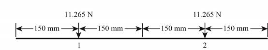
Figure-(1)
The figure-(1) shows the required dimension.
Write the expression for the deflection at point 1 for two element.
Write the expression for the deflection at point 2 for two element.
Write the expression for Rayleigh method for two element.
Write the expression for Rayleigh method for two element.
Write the expression for first critical speed for two element.
Draw the diagram for the three element system.
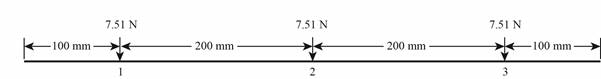
Figure-(2)
The Figure-(2) shows all the dimensions for the three elements.
Write the expression for the deflection at point 1 for three elements
Write the expression for the deflection at point 2 for three element.
Write the expression for the deflection at point 2 for three element.
Write the expression for Rayleigh method for three elements.
Write the expression for Rayleigh method for three elements.
Write the expression for first critical speed for three elements.
Conclusion:
Substitute
Substitute
Substitute
Substitute
Substitute
Calculate the square of the deflection at point 1 of element 1.
Substitute
Substitute
Substitute
Substitute
Substitute
Substitute
Substitute
Substitute
Substitute
Calculate the square of the deflection at point 1 of element 2.
Calculate the square of the deflection at point 2 of element 2.
Substitute
Substitute
Substitute
Substitute
Substitute
Substitute
Substitute
Substitute
Substitute
Substitute
Substitute
Substitute
Calculate the square of the deflection at point 1 of element 3.
Calculate the square of the deflection at point 2 of element 3.
Calculate the square of the deflection at point 3 of element 3.
Substitute
Substitute
Substitute
Since the static bending equation is available, and satisfied the moment-free and deflection-free ends, so the convergence is rapid using a static deflection beam equation.
Thus, the Rayleigh method for uniform diameter shaft is converging rapidly by using a static deflection beam equation.
Want to see more full solutions like this?
Chapter 7 Solutions
Shigley's Mechanical Engineering Design (McGraw-Hill Series in Mechanical Engineering)


- My ID#016948724 please solve this problems and show me every step clear to follow pleasearrow_forwardMy ID# 016948724arrow_forwardPlease do not use any AI tools to solve this question. I need a fully manual, step-by-step solution with clear explanations, as if it were done by a human tutor. No AI-generated responses, please.arrow_forward
- Please do not use any AI tools to solve this question. I need a fully manual, step-by-step solution with clear explanations, as if it were done by a human tutor. No AI-generated responses, please.arrow_forwardPlease do not use any AI tools to solve this question. I need a fully manual, step-by-step solution with clear explanations, as if it were done by a human tutor. No AI-generated responses, please.arrow_forward[Q2]: The cost information supplied by the cost accountant is as follows:Sales 20,00 units, $ 10 per unitCalculate the (a/ newsale guantity and (b) new selling price to earn the sameVariable cost $ 6 per unit, Fixed Cost $ 30,000, Profit $ 50,000profit ifi) Variable cost increases by $ 2 per unitil) Fixed cost increase by $ 10,000Ili) Variable cost increase by $ 1 per unit and fixed cost reduces by $ 10,000arrow_forward
- can you please help me perform Visual Inspection and Fractography of the attatched image: Preliminary examination to identify the fracture origin, suspected fatigue striation, and corrosion evidences.arrow_forwardcan you please help[ me conduct Causal Analysis (FTA) on the scenario attatched: FTA diagram which is a fault tree analysis diagram will be used to gain an overview of the entire path of failure from root cause to the top event (i.e., the swing’s detachment) and to identify interactions between misuse, material decay and inspection errors.arrow_forwardhi can you please help me in finding the stress intensity factor using a k-calcluator for the scenario attathced in the images.arrow_forward
 Mechanics of Materials (MindTap Course List)Mechanical EngineeringISBN:9781337093347Author:Barry J. Goodno, James M. GerePublisher:Cengage Learning