
Videos
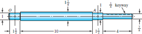
The figure shows a proposed design for the industrial roll shaft of Prob. 7–4. Hydrodynamic film bearings are to be used. All surfaces are machined except the journals, which are ground and polished. The material is 1035 HR steel. Perform a design assessment. Is the design satisfactory?
Problem 7–6
Bearing shoulder fillets 0.030 in, others
Weather the design is satisfactory or not.
Answer to Problem 6P
The design is satisfactory for crown gear.
Explanation of Solution
Write the expression for force acting on roller.
Here, normal force is
Write the expression for force acting on C along z axis.
Here, force on C in z axis is
Write the expression for torque.
Here, torque is
Write the expression for force at B along z axis.
Here, force at B along z axis is
Write the expression for force at B along y-axis
Here, force at B along y-axis is
Write the expression for moment about O.
Write the expression for moment about A.
Write the expression for moment at point C.
Write the expression for moment at A.
Write the expression for moment about O.
Write the expression for moment about A.
Write the expression for moment at point C along z-axis.
Write the expression for moment at A along z-axis.
Write the expression for total moment.
Here, bending moment in x-y plane is
Write the expression for total moment at D.
Here, moment on x-y plane at D is
Write the moment equation in x-y plane.
Integrate Equation (XVI).
Integrate Equation (XVII).
Apply boundary Equation, substitute
Substitute
Substitute
Substitute
Write the moment equation in x-z plane.
Integrate Equation (XVIII).
Integrate Equation (XIX).
Substitute
Substitute
Substitute
Substitute
Write the expression for flexural rigidity.
Here, flexural rigidity is
Write the expression for deflection at A.
Here, speed is
Write the expression for relative deflection.
Here, force is
Write the expression for deflection at B.
Write the expression for deflection at z.
Here, deflection at A is
Write the expression for relative deflection.
Here, force is
Write the expression for deflection at B.
Here, deflection at B is
Write the expression for gear mesh.
Here, gear mesh at B is
Write the expression for concentration factor for bending.
Here, concentration factor for bending is
Write the expression for concentration factor torsion.
Here, concentration factor for torsion is
Write the expression for endurance limit.
Here, endurance limit is
Write the expression for surface factor.
Here, surface factor is
Write the expression for size factor.
Here, size factor is
Write the expression for endurance limit at critical path.
Here, surface modification factor is
Conclusion:
The following figure shows roller forces.
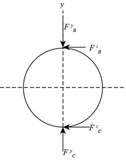
Figure-(1)
Substitute
Substitute
Substitute
Substitute
Substitute
The figure below shows the free body diagram and bending moment diagram.
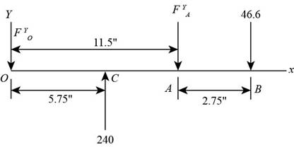
Figure-(2)
Substitute
Substitute
Substitute
The figure below shows the bending moment diagram for x-y plane.
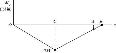
Figure-(3)
Substitute
The figure below shows free body diagram and the bending moment diagram in x-z plane.
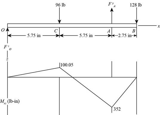
Figure-(4)
Substitute
Substitute
Substitute
Substitute
Substitute
Substitute
The figure below shows the bending moment diagram.
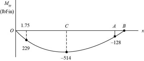
Figure-(5)
The figure below shows the forces in x-z plane.
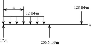
Figure-(6)
Substitute
The figure below shows the bending moment diagram.
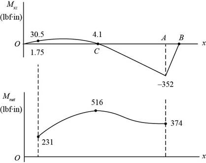
Figure-(7)
Substitute
Substitute
Calculate factor of safety.
The figure below shows forces in x-y plane.
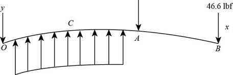
Figure-(8)
Substitute
Substitute
The figure below shows the forces on the system.
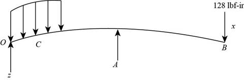
Figure-(9)
Substitute
Substitute
Substitute
Refer to table A-20, “Deterministic ASTM minimum tensile and yield strength for some hot rolled and cold drawn steels” to obtain tensile strength as
Substitute
Substitute
Substitute
Refer to table 7-1, “First iteration estimated for stress concentration factors” to obtain concentration factor for bending stress as
Refer to figure6-20, to obtain notch sensitivity as
Substitute
Substitute
Substitute
Refer to table 6-2, “Parameters for main surface condition factor” to obtain
Substitute
Substitute
Substitute
Substitute
The factor of safety is acceptable for crowned gear.
Thus, crowned gear is more reliable.
Want to see more full solutions like this?
Chapter 7 Solutions
Shigley's Mechanical Engineering Design (McGraw-Hill Series in Mechanical Engineering)


- A press that delivers 115 strokes per minute, each stroke providing a force of 7826 N throughout a distance of 18 mm. The press efficiency is 90% and is driven by a 1749-rpm motor. Determine average torque that must be provided by the motor in the units of N-m.arrow_forward·3) find the force (P) for the figures (1) and (2) 15cm 10cm 15 h=10mm h2=6mm // Call = 90 N/2 P Agate Fig (i) Ans: 1)P=112614N 2) P=1956.5 N 25cm 25 cm الفترة أو الحجم تمر بالتي عثر اكو تورشن (ک Fig (2) h₁ = 10mm 42=6mm Cmarrow_forwardI want a human solutionarrow_forward
- (Read Image)arrow_forward47 14 16 12 34 10 12 12 33arrow_forward3. A steam power plant has an average monthly net power delivery of 740 MW over the course of a year. This power delivery is accomplished by burning coal in the boiler. The coal has a heating value of 9150 Btu/lbm. The cost of the coal is $14.20/ton. The overall thermal efficiency of the plant is, nth = Wnet Qboiler = 0.26 = 26% Determine the annual cost of the coal required to deliver the given average monthly power.arrow_forward
- 47 14 16 12 34 10 12 12 33arrow_forward= The forces F₁ = 590 lb, F₂ = 380 lb, F3 = 240 lb and F 330 lb. Determine the forces in each member of the truss. Use positive values to indicate tension and negative values to indicate compression. a a a D b F₁ A 000 B. 779977 F₂V H G E F4 b BY NC SA 2013 Michael Swanbom Values for dimensions on the figure are given in the following table. Note the figure may not be to scale. Variable Value a 6 ft b 10.1 ft The force in member AB is lb. The force in member AH is lb. The force in member GH is lb. The force in member BH is lb. The force in member BC is lb. The force in member BG is lb. The force in member EG is lb. The force in member CD is lb. The force in member DE is lb. The force in member CE is lb. The force in member CG is lb.arrow_forwardMultiple Choice Circle the best answer to each statement. 1. Which type of surface deviation is controlled by a cy- lindricity tolerance but not by a circularity tolerance? A. B. C. Ovality Taper Lobing D. None of the above 2. When verifying a cylindricity tolerance, the inspec- tion method must be able to collect a set of points and determine the: A. Distance between two coaxial cylinders that con- tain the set of points B. Cylinder that circumscribes the set of points C. Cylinder that inscribes the set of points D. Distance between two coaxial circles that contain the set of points 3. Where Rule #1 applies to a cylindrical regular feature of size, the tolerance value of a cylindricity tolerance applied to the feature of size must be tolerance. A. Less than B. Equal to C. Greater than D. None of the above the size 4. Which of the following modifiers may be applied with a cylindricity tolerance? A. M B. C. ℗ D. Ø 5. Which geometric tolerance can provide an indirect cylindricity…arrow_forward
- The beam AB is attached to the wall in the xz plane by a fixed support at A. A force of F = (−129î + 69.0ĵ + 3591) N is applied to the end of the beam at B. The weight of the beam can be modeled with a uniform distributed load of intensity w = 85.0 N/m acting in the negative z direction along its entire length. Find the support reactions at A. Z с A b a B F y Cc 10 BY NC SA 2016 Eric Davishahl X Values for dimensions on the figure are given in the following. table. Note the figure may not be to scale. Variable Value a 5.60 m b 5.00 m C 3.70 m A II = MA = ( m 2.> ~.> + + k) N k) N-arrow_forwardneed help?arrow_forwardA bent pipe is attached to a wall with brackets as shown. A force of F = 180 lb is applied to the end of the tube with direction indicated by the dimensions in the figure. Determine the support reactions at the brackets B, C, and D. Model these brackets as journal bearings (only force reactions perpendicular to the axis of the tube) and neglect couple moment reactions. Assume the distance between the supports at B and C and the tube bends nearby are negligible such that the support at C is directly above the support at D and the dimension g gives the distance between supports B and C. Enter your answers in Cartesian components. 2013 Michael Swanbom cc 10 BY NC SA g h א B 8° У A C x каж Values for dimensions on the figure are given in the table below. Note the figure may not be to scale. Variable Value a 6.72 in b 11.8 in с 14.8 in d 42.0 in h 26.6 in g 28.0 in → The reaction at B is B = lb. The reaction at C is C = lb. The reaction at D is D = lb. + << + + 2. + + 557 〈んarrow_forward
 Elements Of ElectromagneticsMechanical EngineeringISBN:9780190698614Author:Sadiku, Matthew N. O.Publisher:Oxford University Press
 Mechanics of Materials (10th Edition)Mechanical EngineeringISBN:9780134319650Author:Russell C. HibbelerPublisher:PEARSON
 Thermodynamics: An Engineering ApproachMechanical EngineeringISBN:9781259822674Author:Yunus A. Cengel Dr., Michael A. BolesPublisher:McGraw-Hill Education
 Control Systems EngineeringMechanical EngineeringISBN:9781118170519Author:Norman S. NisePublisher:WILEY
 Mechanics of Materials (MindTap Course List)Mechanical EngineeringISBN:9781337093347Author:Barry J. Goodno, James M. GerePublisher:Cengage Learning
 Engineering Mechanics: StaticsMechanical EngineeringISBN:9781118807330Author:James L. Meriam, L. G. Kraige, J. N. BoltonPublisher:WILEY