
Engineering Mechanics: Statics and Modified Mastering Engineering with eText and Access Card (14th Edition)
14th Edition
ISBN: 9780134229287
Author: Russell C. Hibbeler
Publisher: PEARSON
expand_more
expand_more
format_list_bulleted
Videos
Textbook Question
Chapter 6.6, Problem 68P
Determine the horizontal and vertical components of reaction at all these supports due to the loading shown. 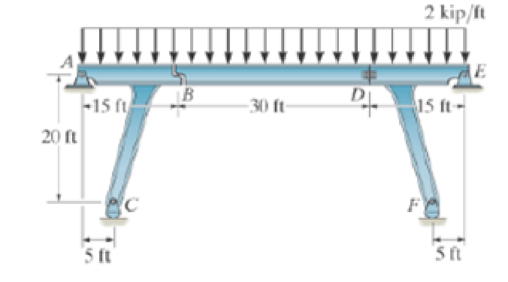
Prob. 6-68
Expert Solution & Answer
Want to see the full answer?
Check out a sample textbook solution
Students have asked these similar questions
The fallowing question is from a reeds book on applied heat i am studying. Although the answer is provided, im struggling to understand the whole answer and the formulas and the steps theyre using. Also where some ov the values such as Hg and Hf come from in part i for example. Please explain step per step in detail thanks
In an NH, refrigerator, the ammonia leaves the evaporatorand enters the cornpressor as dry saturated vapour at 2.68 bar,it leaves the compressor and enters the condenser at 8.57 bar with50" of superheat. it is condensed at constant pressure and leavesthe condenser as saturated liquid. If the rate of flow of the refrigerantthrough the circuit is 0.45 kglmin calculate
(i) the compressorpower,
(ii) the heat rejected to the condenser cooling water in kJ/s,an (iii) the refrigerating effect in kJ/s.
From tables page 12, NH,:2.68 bar, hg= 1430.58.57 bar, hf = 275.1 h supht 50" = 1597.2Mass flow of refrigerant--- - - 0.0075 kgls 60Enthalpy gain per kg of refrigerant in…
state the formulas for calculating work done by gas
Exercises
Find the solution of the following Differential Equations
1) y" + y = 3x²
3)
"+2y+3y=27x
5) y"+y=6sin(x)
7) y"+4y+4y = 18 cosh(x)
9) (4)-5y"+4y = 10 cos(x)
11) y"+y=x²+x
13) y"-2y+y=e*
15) y+2y"-y'-2y=1-4x³
2) y"+2y' + y = x²
4) "+y=-30 sin(4x)
6) y"+4y+3y=sin(x)+2 cos(x)
8) y"-2y+2y= 2e* cos(x)
10) y+y-2y=3e*
12) y"-y=e*
14) y"+y+y=x+4x³ +12x²
16) y"-2y+2y=2e* cos(x)
Chapter 6 Solutions
Engineering Mechanics: Statics and Modified Mastering Engineering with eText and Access Card (14th Edition)
Ch. 6.3 - In each case, calculate the support reactions and...Ch. 6.3 - Identify the zero-force members in each truss....Ch. 6.3 - State if the members are in tension or...Ch. 6.3 - State if the members are in tension or...Ch. 6.3 - State if the members are in tension or...Ch. 6.3 - Determine the greatest load P that can be applied...Ch. 6.3 - Identify the zero-force members in the truss....Ch. 6.3 - State if the members are in tension or...Ch. 6.3 - Set P1 = 20 kN, P2 = 10 kN. Probs. 6-1/2Ch. 6.3 - Set P1 = 45 kN, P2 = 30 kN. Probs. 6-1/2
Ch. 6.3 - State if the members are in tension or...Ch. 6.3 - Determine the force in each member of the truss...Ch. 6.3 - Determine the force in each member of the truss,...Ch. 6.3 - Determine the force in each member of the truss,...Ch. 6.3 - Determine the force in each member of the truss...Ch. 6.3 - Determine the force in each member of the truss...Ch. 6.3 - Determine the force in each member of the truss...Ch. 6.3 - Set P1 = 6 kN, P2 = 9 kN. Probs. 6-9/10Ch. 6.3 - Determine the force in each member of the Pratt...Ch. 6.3 - Determine the force in each member of the truss...Ch. 6.3 - Determine the force in each member of the truss in...Ch. 6.3 - Members AB and BC can each support a maximum...Ch. 6.3 - If a = 6 ft, determine the greatest load P the...Ch. 6.3 - State whether the members are in tension or...Ch. 6.3 - If the maximum force that any member can support...Ch. 6.3 - Set P1 = 10 kN, P2 = 8 kN. Probs. 6-18/19Ch. 6.3 - Determine the force in each member of the truss...Ch. 6.3 - Set P1 = 9 kN, P2 = 15 kN. Probs. 6-20/21Ch. 6.3 - Determine the force in each member of the truss...Ch. 6.3 - Determine the force in each member of the double...Ch. 6.3 - Determine the force in each member of the truss in...Ch. 6.3 - Determine the maximum magnitude of load P that can...Ch. 6.3 - Take P = 2 kN. Probs. 6-25/26Ch. 6.3 - Determine the maximum magnitude P of the two loads...Ch. 6.4 - Determine the force in members BC, CF, and FE....Ch. 6.4 - State if the members are in tension or...Ch. 6.4 - State if the members are in tension or...Ch. 6.4 - State if the members are in tension or...Ch. 6.4 - State if the members are in tension or...Ch. 6.4 - State if the members are in tension or...Ch. 6.4 - Determine the force in members DC, HC, and HI of...Ch. 6.4 - Determine the force in members ED, EH, and GH of...Ch. 6.4 - Determine the force in members HG, HE and DE of...Ch. 6.4 - Determine the force in members CD, HI, and CH of...Ch. 6.4 - State if these members are in tension or...Ch. 6.4 - State if these members are in tension or...Ch. 6.4 - Determine the force in members GF, CD, and GC, and...Ch. 6.4 - Determine the force in members GH, BC, and BG of...Ch. 6.4 - Determine the force in members EF, CF, and BC, and...Ch. 6.4 - Determine the force in members AF, BF, and BC, and...Ch. 6.4 - State if these members are in tension or...Ch. 6.4 - Determine the force in members CD, CF, and CG and...Ch. 6.4 - Determine the force developed in members FE, EB,...Ch. 6.4 - Determine the force in members BC, HC, and HG....Ch. 6.4 - Determine the force in members CD, CJ, GJ, and CG...Ch. 6.4 - Determine the force in members BE, EF, and CB, and...Ch. 6.4 - Determine the force in members BF, BG, and AB, and...Ch. 6.4 - Determine the force in members BC, CH, GH, and CG...Ch. 6.4 - Determine the force in members CD, CJ, and KJ and...Ch. 6.4 - Determine the force in members JK, CJ, and CD of...Ch. 6.4 - Determine the force in members HI, FI, and EF of...Ch. 6.6 - In each case, identify any two-force members, and...Ch. 6.6 - Determine the force P needed to hold the 60-lb...Ch. 6.6 - Determine the horizontal and vertical components...Ch. 6.6 - If a 100-N force is applied to the handles of the...Ch. 6.6 - Determine the horizontal and vertical components...Ch. 6.6 - Determine the normal force that the 100-lb plate A...Ch. 6.6 - Also, determine the proper placement x of the hook...Ch. 6.6 - Determine the components of reaction at A and B....Ch. 6.6 - Determine the reactions at D. Prob. F6-20Ch. 6.6 - Determine the components of reaction at A and C....Ch. 6.6 - Determine the components of reaction at C. Prob....Ch. 6.6 - Determine the components of reaction at E. Prob....Ch. 6.6 - Determine the components of reaction at D and the...Ch. 6.6 - Determine the force P required to hold the 100-lb...Ch. 6.6 - The block weighs 100 lb. Prob. 6-62Ch. 6.6 - Determine the force P required to hold the 50-kg...Ch. 6.6 - Determine the force P required to hold the 150-kg...Ch. 6.6 - Determine the horizontal and vertical components...Ch. 6.6 - Determine the horizontal and vertical components...Ch. 6.6 - Also, what are the horizontal and vertical...Ch. 6.6 - Determine the horizontal and vertical components...Ch. 6.6 - Determine the reactions at supports A and B. Prob....Ch. 6.6 - The suspended cylinder has a mass of 75 kg. Prob....Ch. 6.6 - Determine the reactions at the supports A, C, and...Ch. 6.6 - Determine the resultant force at pins A, B, and C...Ch. 6.6 - Determine the reactions at the supports at A, E,...Ch. 6.6 - Determine the horizontal and vertical components...Ch. 6.6 - Determine the horizontal and vertical components...Ch. 6.6 - Determine the horizontal and vertical components...Ch. 6.6 - Determine the horizontal and vertical components...Ch. 6.6 - There is a hinge (pin) at D. Determine the...Ch. 6.6 - Determine the force P exerted on each of the...Ch. 6.6 - The toggle clamp is subjected to a force F at the...Ch. 6.6 - Determine the force the load creates in member DB...Ch. 6.6 - Determine the compressive force developed on the...Ch. 6.6 - Also, find the horizontal and vertical components...Ch. 6.6 - Also, what are the horizontal and vertical...Ch. 6.6 - Determine the force in the guy cable AI and the...Ch. 6.6 - When the walking beam ABC is horizontal, the force...Ch. 6.6 - Determine the force that the jaws J of the metal...Ch. 6.6 - It consists of two toggles ABC and DBF, which are...Ch. 6.6 - The 600-N load is applied to the pin. Prob. 6-89Ch. 6.6 - If the wheel at A exerts a normal force of FA = 80...Ch. 6.6 - The shovel load has a mass of 1.25 Mg and a center...Ch. 6.6 - Determine the horizontal and vertical components...Ch. 6.6 - Determine the compressive force P that is exerted...Ch. 6.6 - If each coin weighs 0.0235 lb, determine the...Ch. 6.6 - Assuming the blades are pin connected at B and the...Ch. 6.6 - Determine the total force he must exert on bar AB...Ch. 6.6 - Determine the total force he must exert on bar AB...Ch. 6.6 - The cable is attached to D, passes over the smooth...Ch. 6.6 - The grip at B on member DAB resists both...Ch. 6.6 - If the compression in the spring is 20 mm when the...Ch. 6.6 - If a clamping force of 300 N is required at A,...Ch. 6.6 - If a force of F = 350 N is applied to the handle...Ch. 6.6 - Determine the horizontal and vertical components...Ch. 6.6 - Determine the force in the hydraulic cylinder AB...Ch. 6.6 - The spring has a stiffness of k = 6 kN/m. Prob....Ch. 6.6 - If d = 0.75 ft and the spring has an unstretched...Ch. 6.6 - If a force of F = 50 lb is applied to the pads at...Ch. 6.6 - If there is a 300-kg stone in the bucket, with...Ch. 6.6 - when the mechanism is in the position shown. The...Ch. 6.6 - Prob. 110PCh. 6.6 - Prob. 111PCh. 6.6 - If the sprig has a stiffness of k = 15 lb/in., and...Ch. 6.6 - Through this arrangement, a small weight can...Ch. 6.6 - Through this arrangement, a small weight can...Ch. 6.6 - If only vertical forces are supported at the...Ch. 6.6 - Determine the force in each member of the truss...Ch. 6.6 - Determine the force in each member of the truss...Ch. 6.6 - Determine the force in member GJ and GC of the...Ch. 6.6 - Determine the force in members GF, FB, and BC of...Ch. 6.6 - Determine the horizontal and vertical components...Ch. 6.6 - Determine the horizontal and vertical components...Ch. 6.6 - Determine the resultant forces at pins B and C on...
Knowledge Booster


Learn more about
Need a deep-dive on the concept behind this application? Look no further. Learn more about this topic, mechanical-engineering and related others by exploring similar questions and additional content below.Similar questions
- The state of stress at a point is σ = -4.00 kpsi, σy = 16.00 kpsi, σ = -14.00 kpsi, Try = 11.00 kpsi, Tyz = 8.000 kpsi, and T = -14.00 kpsi. Determine the principal stresses. The principal normal stress σ₁ is determined to be [ The principal normal stress σ2 is determined to be [ The principal normal stress σ3 is determined to be kpsi. kpsi. The principal shear stress 71/2 is determined to be [ The principal shear stress 7½ is determined to be [ The principal shear stress T₁/, is determined to be [ kpsi. kpsi. kpsi. kpsi.arrow_forwardRepeat Problem 28, except using a shaft that is rotatingand transmitting a torque of 150 N * m from the left bearing to the middle of the shaft. Also, there is a profile keyseat at the middle under the load. (I want to understand this problem)arrow_forwardProb 2. The material distorts into the dashed position shown. Determine the average normal strains &x, Ey and the shear strain Yxy at A, and the average normal strain along line BE. 50 mm B 200 mm 15 mm 30 mm D ΕΙ 50 mm x A 150 mm Farrow_forward
- Prob 3. The triangular plate is fixed at its base, and its apex A is given a horizontal displacement of 5 mm. Determine the shear strain, Yxy, at A. Prob 4. The triangular plate is fixed at its base, and its apex A is given a horizontal displacement of 5 mm. Determine the average normal strain & along the x axis. Prob 5. The triangular plate is fixed at its base, and its apex A is given a horizontal displacement of 5 mm. Determine the average normal strain &x along the x' axis. x' 45° 800 mm 45° 45% 800 mm 5 mmarrow_forwardAn airplane lands on the straight runaway, originally travelling at 110 ft/s when s = 0. If it is subjected to the decelerations shown, determine the time t' needed to stop the plane and construct the s -t graph for the motion. draw a graph and show all work step by steparrow_forwarddny dn-1y dn-1u dn-24 +a1 + + Any = bi +b₂- + +bnu. dtn dtn-1 dtn-1 dtn-2 a) Let be a root of the characteristic equation 1 sn+a1sn- + +an = : 0. Show that if u(t) = 0, the differential equation has the solution y(t) = e\t. b) Let к be a zero of the polynomial b(s) = b₁s-1+b2sn−2+ Show that if the input is u(t) equation that is identically zero. = .. +bn. ekt, then there is a solution to the differentialarrow_forward
- B 60 ft WAB AB 30% : The crane's telescopic boom rotates with the angular velocity w = 0.06 rad/s and angular acceleration a = 0.07 rad/s². At the same instant, the boom is extending with a constant speed of 0.8 ft/s, measured relative to the boom. Determine the magnitude of the acceleration of point B at this instant.arrow_forwardThe motion of peg P is constrained by the lemniscate curved slot in OB and by the slotted arm OA. (Figure 1) If OA rotates counterclockwise with a constant angular velocity of 0 = 3 rad/s, determine the magnitude of the velocity of peg P at 0 = 30°. Express your answer to three significant figures and include the appropriate units. Determine the magnitude of the acceleration of peg P at 0 = 30°. Express your answer to three significant figures and include the appropriate units. 0 (4 cos 2 0)m² B Aarrow_forward5: The structure shown was designed to support a30-kN load. It consists of a boom AB with a 30 x 50-mmrectangular cross section and a rod BC with a 20-mm-diametercircular cross section. The boom and the rod are connected bya pin at B and are supported by pins and brackets at A and C,respectively.1. Calculate the normal stress in boom AB and rod BC,indicate if in tension or compression.2. Calculate the shear stress of pins at A, B and C.3. Calculate the bearing stresses at A in member AB,and in the bracket.arrow_forward
- 4: The boom AC is a 4-in. square steel tube with a wallthickness of 0.25 in. The boom is supported by the 0.5-in.-diameter pinat A, and the 0.375-in.-diameter cable BC. The working stresses are 25ksi for the cable, 18 ksi for the boom, and 13.6 ksi for shear in the pin.Neglect the weight of the boom.1. Calculate the maximum value of P (kips) based on boom compression and the maximum value of P (kips) based on tension in the cable.2. Calculate the maximum value of P (kips) based on shear in pin.arrow_forward3: A steel strut S serving as a brace for a boat hoist transmits a compressive force P = 54 kN to the deck of a pier as shown in Fig. STR-08. The strut has a hollow square cross section with a wall thickness t =12mm and the angle θ between the strut and the horizontal is 40°. A pin through the strut transmits the compressive force from the strut to two gusset plates G that are welded to the base plate B. Four anchor bolts fasten the base plate to the deck. The diameter of the pin is 20mm, the thickness of the gusset plates is 16mm, the thickness of the base plate is 8mm, and the diameter of the anchor bolts is 12mm. Disregard any friction between the base plate and the deck.1. Determine the shear stress in the pin, in MPa and the shear stress in the anchor bolts, in MPa.2. Determine the bearing stress in the strut holes, in MPa.arrow_forward1. In the figure, the beam, W410x67, with 9 mm web thicknesssubjects the girder, W530x109 with 12 mm web thickness to a shear load,P (kN). 2L – 90 mm × 90 mm × 6 mm with bolts frame the beam to thegirder.Given: S1 = S2 = S5 = 40 mm; S3 = 75 mm; S4 = 110 mmAllowable Stresses are as follows:Bolt shear stress, Fv = 125 MPaBolt bearing stress, Fp = 510 MPa1. Determine the allowable load, P (kN), based on the shearcapacity of the 4 – 25 mm diameter bolts (4 – d1) and calculate the allowable load, P (kN), based on bolt bearing stress on the web of the beam.2. If P = 450 kN, determine the minimum diameter (mm) of 4 – d1based on allowable bolt shear stress and bearing stress of thebeam web.arrow_forward
arrow_back_ios
SEE MORE QUESTIONS
arrow_forward_ios
Recommended textbooks for you
 Elements Of ElectromagneticsMechanical EngineeringISBN:9780190698614Author:Sadiku, Matthew N. O.Publisher:Oxford University Press
 Mechanics of Materials (10th Edition)Mechanical EngineeringISBN:9780134319650Author:Russell C. HibbelerPublisher:PEARSON
 Thermodynamics: An Engineering ApproachMechanical EngineeringISBN:9781259822674Author:Yunus A. Cengel Dr., Michael A. BolesPublisher:McGraw-Hill Education
 Control Systems EngineeringMechanical EngineeringISBN:9781118170519Author:Norman S. NisePublisher:WILEY
 Mechanics of Materials (MindTap Course List)Mechanical EngineeringISBN:9781337093347Author:Barry J. Goodno, James M. GerePublisher:Cengage Learning
 Engineering Mechanics: StaticsMechanical EngineeringISBN:9781118807330Author:James L. Meriam, L. G. Kraige, J. N. BoltonPublisher:WILEY
Elements Of Electromagnetics
Mechanical Engineering
ISBN:9780190698614
Author:Sadiku, Matthew N. O.
Publisher:Oxford University Press
Mechanics of Materials (10th Edition)
Mechanical Engineering
ISBN:9780134319650
Author:Russell C. Hibbeler
Publisher:PEARSON
Thermodynamics: An Engineering Approach
Mechanical Engineering
ISBN:9781259822674
Author:Yunus A. Cengel Dr., Michael A. Boles
Publisher:McGraw-Hill Education
Control Systems Engineering
Mechanical Engineering
ISBN:9781118170519
Author:Norman S. Nise
Publisher:WILEY
Mechanics of Materials (MindTap Course List)
Mechanical Engineering
ISBN:9781337093347
Author:Barry J. Goodno, James M. Gere
Publisher:Cengage Learning
Engineering Mechanics: Statics
Mechanical Engineering
ISBN:9781118807330
Author:James L. Meriam, L. G. Kraige, J. N. Bolton
Publisher:WILEY
Mechanical SPRING DESIGN Strategy and Restrictions in Under 15 Minutes!; Author: Less Boring Lectures;https://www.youtube.com/watch?v=dsWQrzfQt3s;License: Standard Youtube License