
Engineering Mechanics: Statics and Modified Mastering Engineering with eText and Access Card (14th Edition)
14th Edition
ISBN: 9780134229287
Author: Russell C. Hibbeler
Publisher: PEARSON
expand_more
expand_more
format_list_bulleted
Videos
Textbook Question
thumb_up100%
Chapter 6.6, Problem 18FP
Also, determine the proper placement x of the hook for equilibrium. Neglect the weight of the beam.
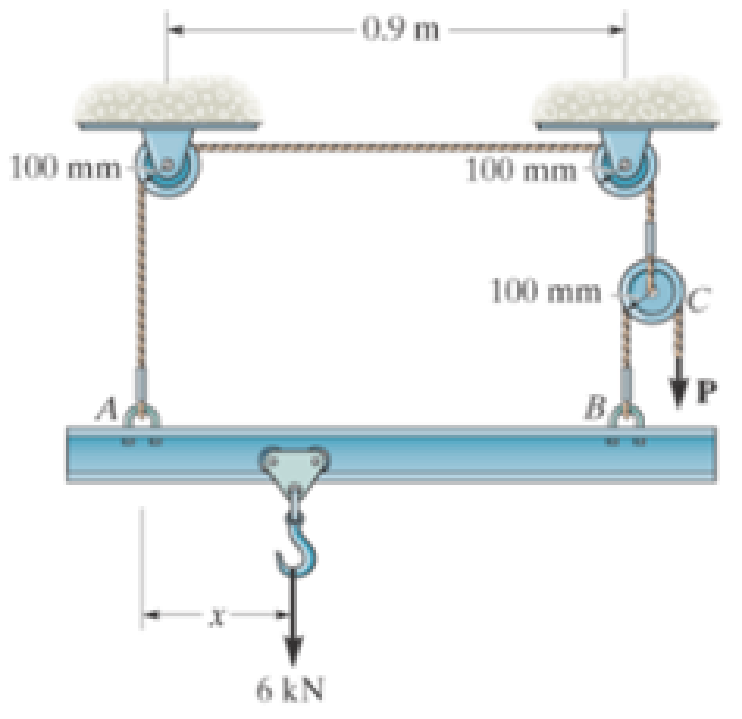
Prob. F6-18
Expert Solution & Answer

Learn your wayIncludes step-by-step video

schedule04:15
Students have asked these similar questions
4. Determine which of the following flow fields represent a possible
incompressible flow?
(a) u= x²+2y+z; v=x-2y+z;w= -2xy + y² + 2z
a
(b) V=U cose
U coso 1 (9)
[1-9]
Usino |1 (4)]
[+]
V=-Usin 1+1
3. Determine the flow rate through the pipe line show in the figure in ft³/s,
and determine the pressures at A and C, in psi.
5'
B
C
12°
20'
D
6"d
2nd-
Water
A
5. A flow is field given by V = x²₁³+xy, and determine
3
·y³j-
(a) Whether this is a one, two- or three-dimensional flow
(b) Whether it is a possible incompressible flow
(c) Determine the acceleration of a fluid particle at the location (X,Y,Z)=(1,2,3)
(d) Whether the flow is rotational or irrotational flow?
Chapter 6 Solutions
Engineering Mechanics: Statics and Modified Mastering Engineering with eText and Access Card (14th Edition)
Ch. 6.3 - In each case, calculate the support reactions and...Ch. 6.3 - Identify the zero-force members in each truss....Ch. 6.3 - State if the members are in tension or...Ch. 6.3 - State if the members are in tension or...Ch. 6.3 - State if the members are in tension or...Ch. 6.3 - Determine the greatest load P that can be applied...Ch. 6.3 - Identify the zero-force members in the truss....Ch. 6.3 - State if the members are in tension or...Ch. 6.3 - Set P1 = 20 kN, P2 = 10 kN. Probs. 6-1/2Ch. 6.3 - Set P1 = 45 kN, P2 = 30 kN. Probs. 6-1/2
Ch. 6.3 - State if the members are in tension or...Ch. 6.3 - Determine the force in each member of the truss...Ch. 6.3 - Determine the force in each member of the truss,...Ch. 6.3 - Determine the force in each member of the truss,...Ch. 6.3 - Determine the force in each member of the truss...Ch. 6.3 - Determine the force in each member of the truss...Ch. 6.3 - Determine the force in each member of the truss...Ch. 6.3 - Set P1 = 6 kN, P2 = 9 kN. Probs. 6-9/10Ch. 6.3 - Determine the force in each member of the Pratt...Ch. 6.3 - Determine the force in each member of the truss...Ch. 6.3 - Determine the force in each member of the truss in...Ch. 6.3 - Members AB and BC can each support a maximum...Ch. 6.3 - If a = 6 ft, determine the greatest load P the...Ch. 6.3 - State whether the members are in tension or...Ch. 6.3 - If the maximum force that any member can support...Ch. 6.3 - Set P1 = 10 kN, P2 = 8 kN. Probs. 6-18/19Ch. 6.3 - Determine the force in each member of the truss...Ch. 6.3 - Set P1 = 9 kN, P2 = 15 kN. Probs. 6-20/21Ch. 6.3 - Determine the force in each member of the truss...Ch. 6.3 - Determine the force in each member of the double...Ch. 6.3 - Determine the force in each member of the truss in...Ch. 6.3 - Determine the maximum magnitude of load P that can...Ch. 6.3 - Take P = 2 kN. Probs. 6-25/26Ch. 6.3 - Determine the maximum magnitude P of the two loads...Ch. 6.4 - Determine the force in members BC, CF, and FE....Ch. 6.4 - State if the members are in tension or...Ch. 6.4 - State if the members are in tension or...Ch. 6.4 - State if the members are in tension or...Ch. 6.4 - State if the members are in tension or...Ch. 6.4 - State if the members are in tension or...Ch. 6.4 - Determine the force in members DC, HC, and HI of...Ch. 6.4 - Determine the force in members ED, EH, and GH of...Ch. 6.4 - Determine the force in members HG, HE and DE of...Ch. 6.4 - Determine the force in members CD, HI, and CH of...Ch. 6.4 - State if these members are in tension or...Ch. 6.4 - State if these members are in tension or...Ch. 6.4 - Determine the force in members GF, CD, and GC, and...Ch. 6.4 - Determine the force in members GH, BC, and BG of...Ch. 6.4 - Determine the force in members EF, CF, and BC, and...Ch. 6.4 - Determine the force in members AF, BF, and BC, and...Ch. 6.4 - State if these members are in tension or...Ch. 6.4 - Determine the force in members CD, CF, and CG and...Ch. 6.4 - Determine the force developed in members FE, EB,...Ch. 6.4 - Determine the force in members BC, HC, and HG....Ch. 6.4 - Determine the force in members CD, CJ, GJ, and CG...Ch. 6.4 - Determine the force in members BE, EF, and CB, and...Ch. 6.4 - Determine the force in members BF, BG, and AB, and...Ch. 6.4 - Determine the force in members BC, CH, GH, and CG...Ch. 6.4 - Determine the force in members CD, CJ, and KJ and...Ch. 6.4 - Determine the force in members JK, CJ, and CD of...Ch. 6.4 - Determine the force in members HI, FI, and EF of...Ch. 6.6 - In each case, identify any two-force members, and...Ch. 6.6 - Determine the force P needed to hold the 60-lb...Ch. 6.6 - Determine the horizontal and vertical components...Ch. 6.6 - If a 100-N force is applied to the handles of the...Ch. 6.6 - Determine the horizontal and vertical components...Ch. 6.6 - Determine the normal force that the 100-lb plate A...Ch. 6.6 - Also, determine the proper placement x of the hook...Ch. 6.6 - Determine the components of reaction at A and B....Ch. 6.6 - Determine the reactions at D. Prob. F6-20Ch. 6.6 - Determine the components of reaction at A and C....Ch. 6.6 - Determine the components of reaction at C. Prob....Ch. 6.6 - Determine the components of reaction at E. Prob....Ch. 6.6 - Determine the components of reaction at D and the...Ch. 6.6 - Determine the force P required to hold the 100-lb...Ch. 6.6 - The block weighs 100 lb. Prob. 6-62Ch. 6.6 - Determine the force P required to hold the 50-kg...Ch. 6.6 - Determine the force P required to hold the 150-kg...Ch. 6.6 - Determine the horizontal and vertical components...Ch. 6.6 - Determine the horizontal and vertical components...Ch. 6.6 - Also, what are the horizontal and vertical...Ch. 6.6 - Determine the horizontal and vertical components...Ch. 6.6 - Determine the reactions at supports A and B. Prob....Ch. 6.6 - The suspended cylinder has a mass of 75 kg. Prob....Ch. 6.6 - Determine the reactions at the supports A, C, and...Ch. 6.6 - Determine the resultant force at pins A, B, and C...Ch. 6.6 - Determine the reactions at the supports at A, E,...Ch. 6.6 - Determine the horizontal and vertical components...Ch. 6.6 - Determine the horizontal and vertical components...Ch. 6.6 - Determine the horizontal and vertical components...Ch. 6.6 - Determine the horizontal and vertical components...Ch. 6.6 - There is a hinge (pin) at D. Determine the...Ch. 6.6 - Determine the force P exerted on each of the...Ch. 6.6 - The toggle clamp is subjected to a force F at the...Ch. 6.6 - Determine the force the load creates in member DB...Ch. 6.6 - Determine the compressive force developed on the...Ch. 6.6 - Also, find the horizontal and vertical components...Ch. 6.6 - Also, what are the horizontal and vertical...Ch. 6.6 - Determine the force in the guy cable AI and the...Ch. 6.6 - When the walking beam ABC is horizontal, the force...Ch. 6.6 - Determine the force that the jaws J of the metal...Ch. 6.6 - It consists of two toggles ABC and DBF, which are...Ch. 6.6 - The 600-N load is applied to the pin. Prob. 6-89Ch. 6.6 - If the wheel at A exerts a normal force of FA = 80...Ch. 6.6 - The shovel load has a mass of 1.25 Mg and a center...Ch. 6.6 - Determine the horizontal and vertical components...Ch. 6.6 - Determine the compressive force P that is exerted...Ch. 6.6 - If each coin weighs 0.0235 lb, determine the...Ch. 6.6 - Assuming the blades are pin connected at B and the...Ch. 6.6 - Determine the total force he must exert on bar AB...Ch. 6.6 - Determine the total force he must exert on bar AB...Ch. 6.6 - The cable is attached to D, passes over the smooth...Ch. 6.6 - The grip at B on member DAB resists both...Ch. 6.6 - If the compression in the spring is 20 mm when the...Ch. 6.6 - If a clamping force of 300 N is required at A,...Ch. 6.6 - If a force of F = 350 N is applied to the handle...Ch. 6.6 - Determine the horizontal and vertical components...Ch. 6.6 - Determine the force in the hydraulic cylinder AB...Ch. 6.6 - The spring has a stiffness of k = 6 kN/m. Prob....Ch. 6.6 - If d = 0.75 ft and the spring has an unstretched...Ch. 6.6 - If a force of F = 50 lb is applied to the pads at...Ch. 6.6 - If there is a 300-kg stone in the bucket, with...Ch. 6.6 - when the mechanism is in the position shown. The...Ch. 6.6 - Prob. 110PCh. 6.6 - Prob. 111PCh. 6.6 - If the sprig has a stiffness of k = 15 lb/in., and...Ch. 6.6 - Through this arrangement, a small weight can...Ch. 6.6 - Through this arrangement, a small weight can...Ch. 6.6 - If only vertical forces are supported at the...Ch. 6.6 - Determine the force in each member of the truss...Ch. 6.6 - Determine the force in each member of the truss...Ch. 6.6 - Determine the force in member GJ and GC of the...Ch. 6.6 - Determine the force in members GF, FB, and BC of...Ch. 6.6 - Determine the horizontal and vertical components...Ch. 6.6 - Determine the horizontal and vertical components...Ch. 6.6 - Determine the resultant forces at pins B and C on...
Additional Engineering Textbook Solutions
Find more solutions based on key concepts
Explain how entities are transformed into tables.
Database Concepts (8th Edition)
Find the error in the following pseudocode. Declare Integer value1, value2, value3, sum Set sum = value1 + valu...
Starting Out with Programming Logic and Design (5th Edition) (What's New in Computer Science)
Automobile Costs Write a program that asks the user to enter the monthly costs for the following expenses incur...
Starting Out with C++ from Control Structures to Objects (9th Edition)
Porter’s competitive forces model: The model is used to provide a general view about the firms, the competitors...
Management Information Systems: Managing The Digital Firm (16th Edition)
Find the no-load value of υo in the circuit shown.
Find υo when RL is 150 Ω.
How much power is dissipated in th...
Electric Circuits. (11th Edition)
int x = 0, y=2; x = y 4; System.out.println(x + \n + y + In);
Starting Out with Java: From Control Structures through Objects (7th Edition) (What's New in Computer Science)
Knowledge Booster


Learn more about
Need a deep-dive on the concept behind this application? Look no further. Learn more about this topic, mechanical-engineering and related others by exploring similar questions and additional content below.Similar questions
- Solve this problem and show all of the workarrow_forwardSolve this problem and show all of the workarrow_forwarddraw the pneumatic circuit to operate a double-acting cylinder with: 1. Extension: Any of two manual conditions plus cylinder fully retracted, → Extension has both meter-in and meter-out, 2. Retraction: one manual conditions plus cylinder fully extended, → Retraction is very fast using quick exhaust valve.arrow_forward
- Correct answer is written below. Detailed and complete solution with fbd only. I will upvote, thank you. Expert solution plsarrow_forwardCorrect answer is written below. Detailed and complete solution with fbd only. I will upvote, thank you.arrow_forwardCorrect answer is written below. Detailed and complete solution with fbd only. I will upvote, thank you.arrow_forward
- Correct answer is written below. Detailed and complete solution only with fbd. I will upvote, thank you.arrow_forwardCorrect answer is written below. Detailed and complete solution only. I will upvote, thank you.arrow_forwardCorrect answer is written below. Detailed and complete solution with fbd only. I will upvote, thank you.arrow_forward
- Correct answer is written below. Detailed and complete solution only. I will upvote, thank you.arrow_forwardCorrect answer is written below. Detailed and complete solution with fbd only. I will upvote, thank you.arrow_forwardCorrect answer is written below. Detailed and complete solution only. I will upvote, thank you.arrow_forward
arrow_back_ios
SEE MORE QUESTIONS
arrow_forward_ios
Recommended textbooks for you
 Elements Of ElectromagneticsMechanical EngineeringISBN:9780190698614Author:Sadiku, Matthew N. O.Publisher:Oxford University Press
 Mechanics of Materials (10th Edition)Mechanical EngineeringISBN:9780134319650Author:Russell C. HibbelerPublisher:PEARSON
 Thermodynamics: An Engineering ApproachMechanical EngineeringISBN:9781259822674Author:Yunus A. Cengel Dr., Michael A. BolesPublisher:McGraw-Hill Education
 Control Systems EngineeringMechanical EngineeringISBN:9781118170519Author:Norman S. NisePublisher:WILEY
 Mechanics of Materials (MindTap Course List)Mechanical EngineeringISBN:9781337093347Author:Barry J. Goodno, James M. GerePublisher:Cengage Learning
 Engineering Mechanics: StaticsMechanical EngineeringISBN:9781118807330Author:James L. Meriam, L. G. Kraige, J. N. BoltonPublisher:WILEY
Elements Of Electromagnetics
Mechanical Engineering
ISBN:9780190698614
Author:Sadiku, Matthew N. O.
Publisher:Oxford University Press
Mechanics of Materials (10th Edition)
Mechanical Engineering
ISBN:9780134319650
Author:Russell C. Hibbeler
Publisher:PEARSON
Thermodynamics: An Engineering Approach
Mechanical Engineering
ISBN:9781259822674
Author:Yunus A. Cengel Dr., Michael A. Boles
Publisher:McGraw-Hill Education
Control Systems Engineering
Mechanical Engineering
ISBN:9781118170519
Author:Norman S. Nise
Publisher:WILEY
Mechanics of Materials (MindTap Course List)
Mechanical Engineering
ISBN:9781337093347
Author:Barry J. Goodno, James M. Gere
Publisher:Cengage Learning
Engineering Mechanics: Statics
Mechanical Engineering
ISBN:9781118807330
Author:James L. Meriam, L. G. Kraige, J. N. Bolton
Publisher:WILEY
Physics 33 - Fluid Statics (1 of 10) Pressure in a Fluid; Author: Michel van Biezen;https://www.youtube.com/watch?v=mzjlAla3H1Q;License: Standard YouTube License, CC-BY