
Engineering Mechanics: Statics and Modified Mastering Engineering with eText and Access Card (14th Edition)
14th Edition
ISBN: 9780134229287
Author: Russell C. Hibbeler
Publisher: PEARSON
expand_more
expand_more
format_list_bulleted
Concept explainers
Videos
Textbook Question
Chapter 6.3, Problem 1P
Set P1 = 20 kN, P2 = 10 kN.
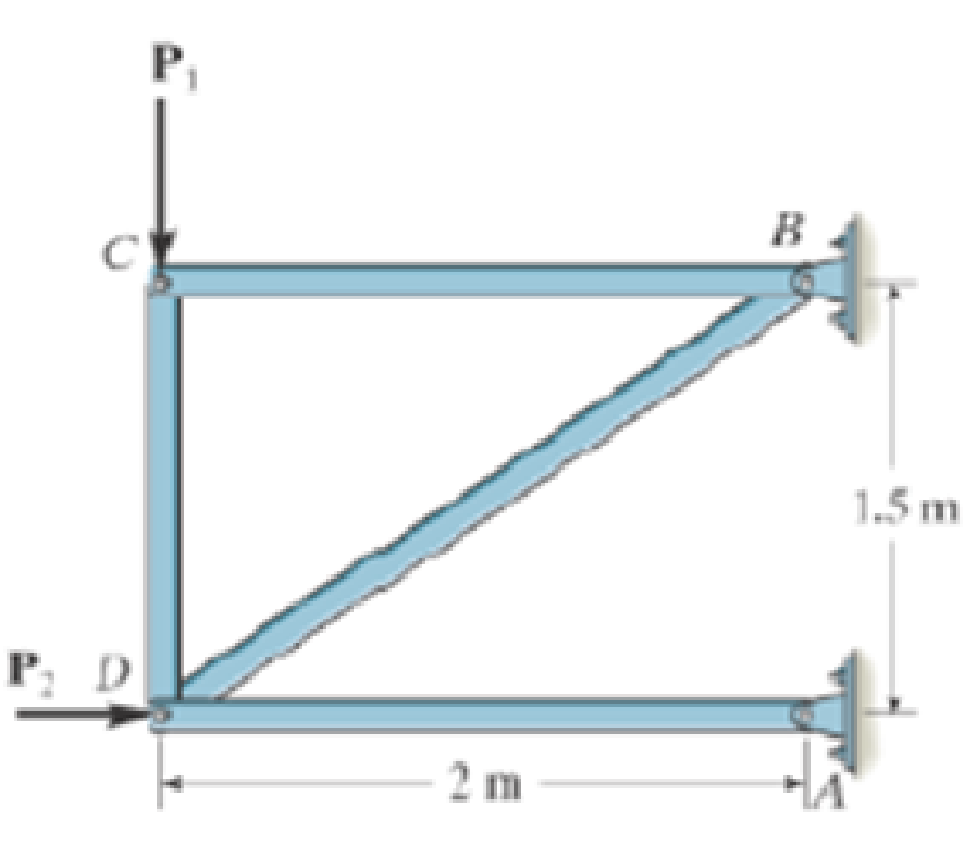
Probs. 6-1/2
Expert Solution & Answer

Learn your wayIncludes step-by-step video

schedule06:10
Students have asked these similar questions
Compute the mass fraction of eutectoid cementite
in an iron-carbon alloy that contains 1.00 wt% C.
Compute the mass fraction of eutectoid cementite
in an iron-carbon alloy that contains 1.00 wt% C.
!
Required information
Mechanical engineering, don't use
chatgpt.
Thanks
A 60-kip-in. torque T is applied to each of the cylinders shown.
NOTE: This is a multi-part question. Once an answer is submitted, you will be unable to return to this part.
3 in.
4 in.
(a)
(b)
Determine the inner diameter of the 4-in. diameter hollow cylinder shown, for which the maximum stress is the same as in part a.
The inner diameter is
in.
Chapter 6 Solutions
Engineering Mechanics: Statics and Modified Mastering Engineering with eText and Access Card (14th Edition)
Ch. 6.3 - In each case, calculate the support reactions and...Ch. 6.3 - Identify the zero-force members in each truss....Ch. 6.3 - State if the members are in tension or...Ch. 6.3 - State if the members are in tension or...Ch. 6.3 - State if the members are in tension or...Ch. 6.3 - Determine the greatest load P that can be applied...Ch. 6.3 - Identify the zero-force members in the truss....Ch. 6.3 - State if the members are in tension or...Ch. 6.3 - Set P1 = 20 kN, P2 = 10 kN. Probs. 6-1/2Ch. 6.3 - Set P1 = 45 kN, P2 = 30 kN. Probs. 6-1/2
Ch. 6.3 - State if the members are in tension or...Ch. 6.3 - Determine the force in each member of the truss...Ch. 6.3 - Determine the force in each member of the truss,...Ch. 6.3 - Determine the force in each member of the truss,...Ch. 6.3 - Determine the force in each member of the truss...Ch. 6.3 - Determine the force in each member of the truss...Ch. 6.3 - Determine the force in each member of the truss...Ch. 6.3 - Set P1 = 6 kN, P2 = 9 kN. Probs. 6-9/10Ch. 6.3 - Determine the force in each member of the Pratt...Ch. 6.3 - Determine the force in each member of the truss...Ch. 6.3 - Determine the force in each member of the truss in...Ch. 6.3 - Members AB and BC can each support a maximum...Ch. 6.3 - If a = 6 ft, determine the greatest load P the...Ch. 6.3 - State whether the members are in tension or...Ch. 6.3 - If the maximum force that any member can support...Ch. 6.3 - Set P1 = 10 kN, P2 = 8 kN. Probs. 6-18/19Ch. 6.3 - Determine the force in each member of the truss...Ch. 6.3 - Set P1 = 9 kN, P2 = 15 kN. Probs. 6-20/21Ch. 6.3 - Determine the force in each member of the truss...Ch. 6.3 - Determine the force in each member of the double...Ch. 6.3 - Determine the force in each member of the truss in...Ch. 6.3 - Determine the maximum magnitude of load P that can...Ch. 6.3 - Take P = 2 kN. Probs. 6-25/26Ch. 6.3 - Determine the maximum magnitude P of the two loads...Ch. 6.4 - Determine the force in members BC, CF, and FE....Ch. 6.4 - State if the members are in tension or...Ch. 6.4 - State if the members are in tension or...Ch. 6.4 - State if the members are in tension or...Ch. 6.4 - State if the members are in tension or...Ch. 6.4 - State if the members are in tension or...Ch. 6.4 - Determine the force in members DC, HC, and HI of...Ch. 6.4 - Determine the force in members ED, EH, and GH of...Ch. 6.4 - Determine the force in members HG, HE and DE of...Ch. 6.4 - Determine the force in members CD, HI, and CH of...Ch. 6.4 - State if these members are in tension or...Ch. 6.4 - State if these members are in tension or...Ch. 6.4 - Determine the force in members GF, CD, and GC, and...Ch. 6.4 - Determine the force in members GH, BC, and BG of...Ch. 6.4 - Determine the force in members EF, CF, and BC, and...Ch. 6.4 - Determine the force in members AF, BF, and BC, and...Ch. 6.4 - State if these members are in tension or...Ch. 6.4 - Determine the force in members CD, CF, and CG and...Ch. 6.4 - Determine the force developed in members FE, EB,...Ch. 6.4 - Determine the force in members BC, HC, and HG....Ch. 6.4 - Determine the force in members CD, CJ, GJ, and CG...Ch. 6.4 - Determine the force in members BE, EF, and CB, and...Ch. 6.4 - Determine the force in members BF, BG, and AB, and...Ch. 6.4 - Determine the force in members BC, CH, GH, and CG...Ch. 6.4 - Determine the force in members CD, CJ, and KJ and...Ch. 6.4 - Determine the force in members JK, CJ, and CD of...Ch. 6.4 - Determine the force in members HI, FI, and EF of...Ch. 6.6 - In each case, identify any two-force members, and...Ch. 6.6 - Determine the force P needed to hold the 60-lb...Ch. 6.6 - Determine the horizontal and vertical components...Ch. 6.6 - If a 100-N force is applied to the handles of the...Ch. 6.6 - Determine the horizontal and vertical components...Ch. 6.6 - Determine the normal force that the 100-lb plate A...Ch. 6.6 - Also, determine the proper placement x of the hook...Ch. 6.6 - Determine the components of reaction at A and B....Ch. 6.6 - Determine the reactions at D. Prob. F6-20Ch. 6.6 - Determine the components of reaction at A and C....Ch. 6.6 - Determine the components of reaction at C. Prob....Ch. 6.6 - Determine the components of reaction at E. Prob....Ch. 6.6 - Determine the components of reaction at D and the...Ch. 6.6 - Determine the force P required to hold the 100-lb...Ch. 6.6 - The block weighs 100 lb. Prob. 6-62Ch. 6.6 - Determine the force P required to hold the 50-kg...Ch. 6.6 - Determine the force P required to hold the 150-kg...Ch. 6.6 - Determine the horizontal and vertical components...Ch. 6.6 - Determine the horizontal and vertical components...Ch. 6.6 - Also, what are the horizontal and vertical...Ch. 6.6 - Determine the horizontal and vertical components...Ch. 6.6 - Determine the reactions at supports A and B. Prob....Ch. 6.6 - The suspended cylinder has a mass of 75 kg. Prob....Ch. 6.6 - Determine the reactions at the supports A, C, and...Ch. 6.6 - Determine the resultant force at pins A, B, and C...Ch. 6.6 - Determine the reactions at the supports at A, E,...Ch. 6.6 - Determine the horizontal and vertical components...Ch. 6.6 - Determine the horizontal and vertical components...Ch. 6.6 - Determine the horizontal and vertical components...Ch. 6.6 - Determine the horizontal and vertical components...Ch. 6.6 - There is a hinge (pin) at D. Determine the...Ch. 6.6 - Determine the force P exerted on each of the...Ch. 6.6 - The toggle clamp is subjected to a force F at the...Ch. 6.6 - Determine the force the load creates in member DB...Ch. 6.6 - Determine the compressive force developed on the...Ch. 6.6 - Also, find the horizontal and vertical components...Ch. 6.6 - Also, what are the horizontal and vertical...Ch. 6.6 - Determine the force in the guy cable AI and the...Ch. 6.6 - When the walking beam ABC is horizontal, the force...Ch. 6.6 - Determine the force that the jaws J of the metal...Ch. 6.6 - It consists of two toggles ABC and DBF, which are...Ch. 6.6 - The 600-N load is applied to the pin. Prob. 6-89Ch. 6.6 - If the wheel at A exerts a normal force of FA = 80...Ch. 6.6 - The shovel load has a mass of 1.25 Mg and a center...Ch. 6.6 - Determine the horizontal and vertical components...Ch. 6.6 - Determine the compressive force P that is exerted...Ch. 6.6 - If each coin weighs 0.0235 lb, determine the...Ch. 6.6 - Assuming the blades are pin connected at B and the...Ch. 6.6 - Determine the total force he must exert on bar AB...Ch. 6.6 - Determine the total force he must exert on bar AB...Ch. 6.6 - The cable is attached to D, passes over the smooth...Ch. 6.6 - The grip at B on member DAB resists both...Ch. 6.6 - If the compression in the spring is 20 mm when the...Ch. 6.6 - If a clamping force of 300 N is required at A,...Ch. 6.6 - If a force of F = 350 N is applied to the handle...Ch. 6.6 - Determine the horizontal and vertical components...Ch. 6.6 - Determine the force in the hydraulic cylinder AB...Ch. 6.6 - The spring has a stiffness of k = 6 kN/m. Prob....Ch. 6.6 - If d = 0.75 ft and the spring has an unstretched...Ch. 6.6 - If a force of F = 50 lb is applied to the pads at...Ch. 6.6 - If there is a 300-kg stone in the bucket, with...Ch. 6.6 - when the mechanism is in the position shown. The...Ch. 6.6 - Prob. 110PCh. 6.6 - Prob. 111PCh. 6.6 - If the sprig has a stiffness of k = 15 lb/in., and...Ch. 6.6 - Through this arrangement, a small weight can...Ch. 6.6 - Through this arrangement, a small weight can...Ch. 6.6 - If only vertical forces are supported at the...Ch. 6.6 - Determine the force in each member of the truss...Ch. 6.6 - Determine the force in each member of the truss...Ch. 6.6 - Determine the force in member GJ and GC of the...Ch. 6.6 - Determine the force in members GF, FB, and BC of...Ch. 6.6 - Determine the horizontal and vertical components...Ch. 6.6 - Determine the horizontal and vertical components...Ch. 6.6 - Determine the resultant forces at pins B and C on...
Additional Engineering Textbook Solutions
Find more solutions based on key concepts
T F Static local variables are not destroyed when a function returns.
Starting Out with C++ from Control Structures to Objects (9th Edition)
Use the following tables for your answers to questions 3.7 through 3.51 : PET_OWNER (OwnerID, OwnerLasst Name, ...
Database Concepts (8th Edition)
In what year was Plankalkl designed? In what year was that design published?
Concepts Of Programming Languages
Which of the following activities require real-time processing? a. Printing mailing labels b. Playing a compute...
Computer Science: An Overview (13th Edition) (What's New in Computer Science)
A(n) _____ is a component of a class that references data. a. method b. instance c. data attribute d. module
Starting Out with Python (4th Edition)
The ____________ is always transparent.
Web Development and Design Foundations with HTML5 (8th Edition)
Knowledge Booster


Learn more about
Need a deep-dive on the concept behind this application? Look no further. Learn more about this topic, mechanical-engineering and related others by exploring similar questions and additional content below.Similar questions
- Mechanical engineering, Don't use chatgpt. Strict warning.arrow_forward10:38 PM P 4136 54 A man Homework was due west for and 4km. He then changes directies walks on a bearing south-wes IS How far Point? of 1970 until he of his Starting Port Is he then from his stating What do you think about ... ||| Մ כarrow_forwardA simply supported T-shaped beam of 6m in length has to be designed to carry an inclined central point load W. Find the max- imum value of this load such that the maximum tensile and com- pression stresses on the beam do not exceed 30 and 60 respectively. N mm² N mm², 90 mm 80 mm Y W 60 mm 30° 10 mm 10 mm Xarrow_forward
- Problem 9.5 9.5 A 1080-kg car is parked on a sloped street. The figure shows its wheels and the position of its center of mass. The street is icy, and as a result the coefficient of static friction between the car's tires and the street surface is μs = 0.2. Determine the steepest slope (in degrees relative to the horizontal) at which the car could remain in equilibrium if a. the brakes are applied to both its front and rear wheels; b. the brakes are applied to the front (lower) wheels only. Problem 9.5 1380 mm 532 mm 2370 mmarrow_forwardCan someone explain please with conversionsarrow_forwardCorrect Answer is written below. Detailed and complete fbd only please. I will upvote, thank you. 1: The assembly shown is composed of a rigid plank ABC, supported by hinge at A, spring at B and cable at C.The cable is attached to a frictionless pulley at D and rigidly supported at E. The cable is made of steel with E = 200,000MPa and cross-sectional area of 500 mm2. The details of pulley at D is shown. The pulley is supported by a pin, passingthough the pulley and attached to both cheeks. Note that E is directly above B.Given: H = 3 m; L1 = 2 m; L2 = 4 m; w = 12 kN/m; x:y = 3:4Spring Parameters:Wire diameter = 30 mmMean Radius = 90 mmNumber of turns = 12Modulus of Rigidity = 80 GPaAllowable stresses:Allowable shear stress of Pin at D = 85 MPaAllowable normal stress of cheek at D = 90MPaAllowable bearing stress of cheek at D = 110MPa1. Calculate the reaction of spring Band tension in cable at C.2. Calculate the vertical displacementat C and the required diameter ofpin at D.3.…arrow_forward
- Correct answer and complete fbd only. I will upvote. The compound shaft, composed of steel,aluminum, and bronze segments, carries the two torquesshown in the figure. If TC = 250 lb-ft, determine the maximumshear stress developed in each material (in ksi). The moduliof rigidity for steel, aluminum, and bronze are 12 x 106 psi, 4x 10⁶ psi, and 6 x 10⁶ psi, respectivelyarrow_forwardCan you explain the algebra steps that aren't shown but stated to be there, on how to get this equationarrow_forwardCorrect answer and complete fbd only. I will upvote. A flanged bolt coupling consists of two concentric rows of bolts. The inner row has 6 nos. of 16mm diameterbolts spaced evenly in a circle of 250mm in diameter. The outer row of has 10 nos. of 25 mm diameter bolts spaced evenly in a circle of 500mm in diameter. If the allowable shear stress on one bolt is 60 MPa, determine the torque capacity of the coupling. The Poisson’s ratio of the inner row of bolts is 0.2 while that of the outer row is 0.25 and the bolts are steel, E =200 GPa.arrow_forward
- Correct answer and complete fbd only. I will upvote. 10: The constant wall thickness of a steel tube with the cross sectionshown is 2 mm. If a 600-N-m torque is applied to the tube. Use G = 80 GPa forsteel.1. Find the shear stress (MPa) in the wall of the tube.2. Find the angle of twist, in degrees per meter of length.arrow_forwardCORRECT ANSWER WITH COMPLETE FBD ONLY. I WILL UPVOTE. A torque wrench is used to tighten the pipe shown.Dimensions: S1 = 400 mm; S2 = 250 mm; S3 = 100 mmModulus of Rigidity G = 78 GPa1. The diameter of the solid pipe is 20 mm. How much is themaximum force P (N) that can be applied based on theallowable shear stress of 60 MPa?2. For a hollow pipe with 50 mm outside diameter and is 6 mmthick, compute for the maximum force P (kN) that can beapplied such that the angle of twist at A does not exceed 5degrees.3. The torque applied to tighten the hollow pipe is 200 N-m.Given: Pipe outside diameter = 50 mm Pipe thickness = 6 mmSolve for the resulting maximum shear stress (MPa) in the pipe.arrow_forwardCorrect answer and complete fbd only. I will upvote. 6: The shaft carries a total torque T0 that is uniformly distributedover its length L. Determine the angle of twist (degrees) of the shaft in termsif T0 = 1.2 kN-m, L = 2 m, G = 80 GPa, and diameter = 120 mm.arrow_forward
arrow_back_ios
SEE MORE QUESTIONS
arrow_forward_ios
Recommended textbooks for you
 Elements Of ElectromagneticsMechanical EngineeringISBN:9780190698614Author:Sadiku, Matthew N. O.Publisher:Oxford University Press
 Mechanics of Materials (10th Edition)Mechanical EngineeringISBN:9780134319650Author:Russell C. HibbelerPublisher:PEARSON
 Thermodynamics: An Engineering ApproachMechanical EngineeringISBN:9781259822674Author:Yunus A. Cengel Dr., Michael A. BolesPublisher:McGraw-Hill Education
 Control Systems EngineeringMechanical EngineeringISBN:9781118170519Author:Norman S. NisePublisher:WILEY
 Mechanics of Materials (MindTap Course List)Mechanical EngineeringISBN:9781337093347Author:Barry J. Goodno, James M. GerePublisher:Cengage Learning
 Engineering Mechanics: StaticsMechanical EngineeringISBN:9781118807330Author:James L. Meriam, L. G. Kraige, J. N. BoltonPublisher:WILEY
Elements Of Electromagnetics
Mechanical Engineering
ISBN:9780190698614
Author:Sadiku, Matthew N. O.
Publisher:Oxford University Press
Mechanics of Materials (10th Edition)
Mechanical Engineering
ISBN:9780134319650
Author:Russell C. Hibbeler
Publisher:PEARSON
Thermodynamics: An Engineering Approach
Mechanical Engineering
ISBN:9781259822674
Author:Yunus A. Cengel Dr., Michael A. Boles
Publisher:McGraw-Hill Education
Control Systems Engineering
Mechanical Engineering
ISBN:9781118170519
Author:Norman S. Nise
Publisher:WILEY
Mechanics of Materials (MindTap Course List)
Mechanical Engineering
ISBN:9781337093347
Author:Barry J. Goodno, James M. Gere
Publisher:Cengage Learning
Engineering Mechanics: Statics
Mechanical Engineering
ISBN:9781118807330
Author:James L. Meriam, L. G. Kraige, J. N. Bolton
Publisher:WILEY
Engineering Basics - Statics & Forces in Equilibrium; Author: Solid Solutions - Professional Design Solutions;https://www.youtube.com/watch?v=dQBvQ2hJZFg;License: Standard YouTube License, CC-BY