
PEARSON ETEXT ENGINEERING MECH & STATS
15th Edition
ISBN: 9780137514724
Author: HIBBELER
Publisher: PEARSON
expand_more
expand_more
format_list_bulleted
Videos
Textbook Question
Chapter 6, Problem 78P
The compound beam is pin supported at B and supported by rockers at A and C. There is a hinge (pin) at D. Determine the reactions at the supports.
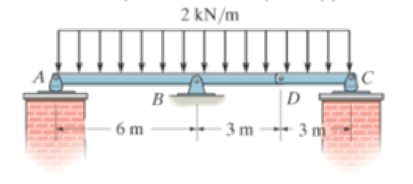
Prob. 6-78
Expert Solution & Answer
Want to see the full answer?
Check out a sample textbook solution
Students have asked these similar questions
The ventilating fan of the bathroom of a building has a volume flow rate of 33 L/s and runs continuously. If the density of air inside is 1.20 kg/m3, determine the mass of air vented out in one day.
The mass of air is kg.
A steady-flow compressor is used to compress helium from 15 psia and 70°F at the inlet to 200 psia and 600°F at the outlet. The outlet area and velocity are 0.01 ft2 and 100 ft/s, respectively, and the inlet velocity is 53 ft/s. Determine the mass flow rate and the inlet area. The gas constant of helium is R = 2.6809 psia·ft3/lbm·R.
The mass flow rate is lbm/s.
The inlet area is ft2.
1. The maximum and minimum stresses as well as the shear stress seen subjected the piece in plane A-A. Assume it is a cylinder with a diameter of 12.7mm 2. Draw the Mohr circle for the stress state using software. 3. Selection of the material for the prosthesis, which must be analyzed from the point of safety and cost view.
Chapter 6 Solutions
PEARSON ETEXT ENGINEERING MECH & STATS
Ch. 6 - Determine the force in each member of the truss....Ch. 6 - Determine the force in each member of the truss....Ch. 6 - Determine the force in each member of the truss....Ch. 6 - Determine the greatest load P that can be applied...Ch. 6 - Identify the zero-force members in the truss....Ch. 6 - Determine the force in each member of the truss....Ch. 6 - Determine the force in each member of the truss...Ch. 6 - Determine the force in each member of the truss...Ch. 6 - Determine the force in each member of the truss...Ch. 6 - Determine the force in each member of the truss in...
Ch. 6 - Members AB and BC can each support a maximum...Ch. 6 - Members AB and BC can each support a maximum...Ch. 6 - Determine the force in each member of the truss....Ch. 6 - If the maximum force that any member can support...Ch. 6 - Determine the force in each member of the truss...Ch. 6 - Determine the force in each member of the truss...Ch. 6 - Prob. 22PCh. 6 - Determine the force in members BC, CF, and FE....Ch. 6 - Determine the force in members LK, KC, and CD of...Ch. 6 - Determine the force in members KJ, KD, and CD of...Ch. 6 - Determine the force in members EF, CF, and BC of...Ch. 6 - Determine the force in members DC, HC, and HI of...Ch. 6 - Determine the force in members ED, EH, and GH of...Ch. 6 - Determine the force in members HG, HE and DE of...Ch. 6 - Determine the force in members CD, HI, and CH of...Ch. 6 - Prob. 39PCh. 6 - Determine the force in members CD, CF, and CG and...Ch. 6 - Determine the force developed in members FE, EB,...Ch. 6 - Determine the force in members CD, CJ, GJ, and CG...Ch. 6 - Prob. 48PCh. 6 - Determine the force in members HI, FI, and EF of...Ch. 6 - Determine the force P needed to hold the 60-lb...Ch. 6 - Determine the horizontal and vertical components...Ch. 6 - If a 100-N force is applied to the handles of the...Ch. 6 - Determine the normal force that the 100-lb plate A...Ch. 6 - Determine the force P needed to lift the load....Ch. 6 - Prob. 19FPCh. 6 - Prob. 20FPCh. 6 - Determine the components of reaction at A and C....Ch. 6 - Determine the components of reaction at C. Prob....Ch. 6 - Determine the components of reaction at E. Prob....Ch. 6 - Determine the components of reaction at D and the...Ch. 6 - Determine the force P required to hold the 100-lb...Ch. 6 - Determine the horizontal and vertical components...Ch. 6 - The bridge frame consists of three segments which...Ch. 6 - Determine the reactions at supports A and B. Prob....Ch. 6 - Determine the horizontal and vertical components...Ch. 6 - The compound beam is pin supported at B and...Ch. 6 - When a force of 2 lb is applied to the handles of...Ch. 6 - The hoist supports the 125-kg engine. Determine...Ch. 6 - Prob. 88PCh. 6 - Determine the horizontal and vertical components...Ch. 6 - The pipe cutter is clamped around the pipe P. If...Ch. 6 - Five coins are stacked in the smooth plastic...Ch. 6 - The nail cutter consists of the handle and the two...Ch. 6 - A man having a weight of 175 lb attempts to hold...Ch. 6 - Prob. 97PCh. 6 - If a force of F = 350 N is applied to the handle...Ch. 6 - Prob. 106PCh. 6 - If a force of F = 50 lb is applied to the pads at...Ch. 6 - The spring has an unstretched length of 0.3 m....Ch. 6 - The spring has an unstretched length of 0.3 m....Ch. 6 - The piston C moves vertically between the two...Ch. 6 - Prob. 113PCh. 6 - The platform scale consists of a combination of...Ch. 6 - The three pin-connected members shown in the top...Ch. 6 - Determine the force in each member of the truss...Ch. 6 - Determine the force in each member of the truss...Ch. 6 - Determine the force in member GJ and GC of the...Ch. 6 - Determine the force in members GF, FB, and BC of...Ch. 6 - Determine the horizontal and vertical components...Ch. 6 - Determine the horizontal and vertical components...Ch. 6 - Determine the resultant forces at pins B and C on...
Knowledge Booster


Learn more about
Need a deep-dive on the concept behind this application? Look no further. Learn more about this topic, mechanical-engineering and related others by exploring similar questions and additional content below.Similar questions
- 1. The maximum and minimum stresses as well as the shear stress seen subjected the piece in plane A-A. Assume it is a cylinder with a diameter of 12.7mm 2. Draw the Mohr circle for the stress state using software. 3. Selection of the material for the prosthesis, which must be analyzed from the point of safety and cost view.arrow_forwardFirst, define the coordinate system XY with its origin at O2 and X-axis passing through O4 asshown above, then based on the provided steps Perform coordinate transformation from XY to xy to get the trajectory of point P. Show all the steps and calcualtionsarrow_forwardI don't know how to solve thisarrow_forward
- Question 2 (40 Points) Consider the following double pendulum-like system with links ₁ and 12. The angles 0 and & could have angular velocities ėêk and êk, respectively, where ②k is a unit vector that points out of the page and is perpendicular to x and y. They could also have angular accelerations Ök and êk. The angle is defined relative to the angle 0. The link 12 is a spring and can extend or compress at a rate of 12. It can also have a rate of extension or compression Ï2. li y êr1 êe 12 χ 3 еф er2 ده لج 1) Express the velocity of the mass in terms of the unit vectors ê0, êr1, êø, and êr2, and any extension/contraction of the links (e.g.,. i; and Ï¿) (12 Points) 2) Express the acceleration of the mass in terms of the unit vectors ê¤, ê×1, êp, and êÃ2, and any extension/contraction of the links (e.g.,. İ; and Ï¿) (12 Points) 3) Express the velocity of the mass in terms of unit vectors î and ĵ that point in the x and y directions, respectively. Also include the appropriate,…arrow_forwardprovide step by step solutions for angles teta 3 and teta 4 by the vector loopmethod. Show work in: vector loop, vector equations, solution procedure.arrow_forward(Manometer) A tank is constructed of a series of cylinders having diameters of 0.35, 0.30, and 0.20 m as shown in the figure below. The tank contains oil, water, and glycerin and a mercury manometer is attached to the bottom as illustrated. Calculate the manometer reading, h. 0.11 m + SAE 30 Oil 0.13 m + Water 0.10 m Glycerin + 0.10 m Mercury h = marrow_forward
- P = A piston having a cross-sectional area of 0.40 m² is located in a cylinder containing water as shown in the figure below. An open U-tube manometer is connected to the cylinder as shown. For h₁ = 83 mm and h = 111 mm what is the value of the applied force, P, acting on the piston? The weight of the piston is negligible. Hi 5597.97 N P Piston Water Mercuryarrow_forwardStudent Name: Student Id: College of Applied Engineering Al-Muzahmiyah Branch Statics (AGE 1330) Section-1483 Quiz-2 Time: 20 minutes Date: 16/02/2025 Q.1. A swinging door that weighs w=400.0N is supported by hinges A and B so that the door can swing about a vertical' axis passing through the hinges (as shown in below figure). The door has a width of b=1.00m and the door slab has a uniform mass density. The hinges are placed symmetrically at the door's edge in such a way that the door's weight is evenly distributed between them. The hinges are separated by distance a=2.00m. Find the forces on the hinges when the door rests half-open. Draw Free body diagram also. [5 marks] [CLO 1.2] Mool b ర a 2.0 m B 1.0 marrow_forwardFor the walking-beam mechanism shown in Figure 3, find and plot the x and y coordinates of the position of the coupler point P for one complete revolution of the crank O2A. Use the coordinate system shown in Figure 3. Hint: Calculate them first with respect to the ground link 0204 and then transform them into the global XY coordinate system. y -1.75 Ꮎ Ꮎ 4 = 2.33 0242.22 L4 x AP = 3.06 L2 = 1.0 W2 31° B 03 L3 = 2.06 P 1 8 5 .06 6 7 P'arrow_forward
arrow_back_ios
SEE MORE QUESTIONS
arrow_forward_ios
Recommended textbooks for you
 Elements Of ElectromagneticsMechanical EngineeringISBN:9780190698614Author:Sadiku, Matthew N. O.Publisher:Oxford University Press
 Mechanics of Materials (10th Edition)Mechanical EngineeringISBN:9780134319650Author:Russell C. HibbelerPublisher:PEARSON
 Thermodynamics: An Engineering ApproachMechanical EngineeringISBN:9781259822674Author:Yunus A. Cengel Dr., Michael A. BolesPublisher:McGraw-Hill Education
 Control Systems EngineeringMechanical EngineeringISBN:9781118170519Author:Norman S. NisePublisher:WILEY
 Mechanics of Materials (MindTap Course List)Mechanical EngineeringISBN:9781337093347Author:Barry J. Goodno, James M. GerePublisher:Cengage Learning
 Engineering Mechanics: StaticsMechanical EngineeringISBN:9781118807330Author:James L. Meriam, L. G. Kraige, J. N. BoltonPublisher:WILEY
Elements Of Electromagnetics
Mechanical Engineering
ISBN:9780190698614
Author:Sadiku, Matthew N. O.
Publisher:Oxford University Press
Mechanics of Materials (10th Edition)
Mechanical Engineering
ISBN:9780134319650
Author:Russell C. Hibbeler
Publisher:PEARSON
Thermodynamics: An Engineering Approach
Mechanical Engineering
ISBN:9781259822674
Author:Yunus A. Cengel Dr., Michael A. Boles
Publisher:McGraw-Hill Education
Control Systems Engineering
Mechanical Engineering
ISBN:9781118170519
Author:Norman S. Nise
Publisher:WILEY
Mechanics of Materials (MindTap Course List)
Mechanical Engineering
ISBN:9781337093347
Author:Barry J. Goodno, James M. Gere
Publisher:Cengage Learning
Engineering Mechanics: Statics
Mechanical Engineering
ISBN:9781118807330
Author:James L. Meriam, L. G. Kraige, J. N. Bolton
Publisher:WILEY
Physics 33 - Fluid Statics (1 of 10) Pressure in a Fluid; Author: Michel van Biezen;https://www.youtube.com/watch?v=mzjlAla3H1Q;License: Standard YouTube License, CC-BY