
PEARSON ETEXT ENGINEERING MECH & STATS
15th Edition
ISBN: 9780137514724
Author: HIBBELER
Publisher: PEARSON
expand_more
expand_more
format_list_bulleted
Videos
Textbook Question
Chapter 6, Problem 81P
The hoist supports the 125-kg engine. Determine the force the load creates in member DB and in member FB, which contains the hydraulic cylinder H.
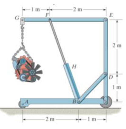
Prob. 6-81
Expert Solution & Answer
Want to see the full answer?
Check out a sample textbook solution
Students have asked these similar questions
(read me)
(read image)
(read image)
Chapter 6 Solutions
PEARSON ETEXT ENGINEERING MECH & STATS
Ch. 6 - Determine the force in each member of the truss....Ch. 6 - Determine the force in each member of the truss....Ch. 6 - Determine the force in each member of the truss....Ch. 6 - Determine the greatest load P that can be applied...Ch. 6 - Identify the zero-force members in the truss....Ch. 6 - Determine the force in each member of the truss....Ch. 6 - Determine the force in each member of the truss...Ch. 6 - Determine the force in each member of the truss...Ch. 6 - Determine the force in each member of the truss...Ch. 6 - Determine the force in each member of the truss in...
Ch. 6 - Members AB and BC can each support a maximum...Ch. 6 - Members AB and BC can each support a maximum...Ch. 6 - Determine the force in each member of the truss....Ch. 6 - If the maximum force that any member can support...Ch. 6 - Determine the force in each member of the truss...Ch. 6 - Determine the force in each member of the truss...Ch. 6 - Prob. 22PCh. 6 - Determine the force in members BC, CF, and FE....Ch. 6 - Determine the force in members LK, KC, and CD of...Ch. 6 - Determine the force in members KJ, KD, and CD of...Ch. 6 - Determine the force in members EF, CF, and BC of...Ch. 6 - Determine the force in members DC, HC, and HI of...Ch. 6 - Determine the force in members ED, EH, and GH of...Ch. 6 - Determine the force in members HG, HE and DE of...Ch. 6 - Determine the force in members CD, HI, and CH of...Ch. 6 - Prob. 39PCh. 6 - Determine the force in members CD, CF, and CG and...Ch. 6 - Determine the force developed in members FE, EB,...Ch. 6 - Determine the force in members CD, CJ, GJ, and CG...Ch. 6 - Prob. 48PCh. 6 - Determine the force in members HI, FI, and EF of...Ch. 6 - Determine the force P needed to hold the 60-lb...Ch. 6 - Determine the horizontal and vertical components...Ch. 6 - If a 100-N force is applied to the handles of the...Ch. 6 - Determine the normal force that the 100-lb plate A...Ch. 6 - Determine the force P needed to lift the load....Ch. 6 - Prob. 19FPCh. 6 - Prob. 20FPCh. 6 - Determine the components of reaction at A and C....Ch. 6 - Determine the components of reaction at C. Prob....Ch. 6 - Determine the components of reaction at E. Prob....Ch. 6 - Determine the components of reaction at D and the...Ch. 6 - Determine the force P required to hold the 100-lb...Ch. 6 - Determine the horizontal and vertical components...Ch. 6 - The bridge frame consists of three segments which...Ch. 6 - Determine the reactions at supports A and B. Prob....Ch. 6 - Determine the horizontal and vertical components...Ch. 6 - The compound beam is pin supported at B and...Ch. 6 - When a force of 2 lb is applied to the handles of...Ch. 6 - The hoist supports the 125-kg engine. Determine...Ch. 6 - Prob. 88PCh. 6 - Determine the horizontal and vertical components...Ch. 6 - The pipe cutter is clamped around the pipe P. If...Ch. 6 - Five coins are stacked in the smooth plastic...Ch. 6 - The nail cutter consists of the handle and the two...Ch. 6 - A man having a weight of 175 lb attempts to hold...Ch. 6 - Prob. 97PCh. 6 - If a force of F = 350 N is applied to the handle...Ch. 6 - Prob. 106PCh. 6 - If a force of F = 50 lb is applied to the pads at...Ch. 6 - The spring has an unstretched length of 0.3 m....Ch. 6 - The spring has an unstretched length of 0.3 m....Ch. 6 - The piston C moves vertically between the two...Ch. 6 - Prob. 113PCh. 6 - The platform scale consists of a combination of...Ch. 6 - The three pin-connected members shown in the top...Ch. 6 - Determine the force in each member of the truss...Ch. 6 - Determine the force in each member of the truss...Ch. 6 - Determine the force in member GJ and GC of the...Ch. 6 - Determine the force in members GF, FB, and BC of...Ch. 6 - Determine the horizontal and vertical components...Ch. 6 - Determine the horizontal and vertical components...Ch. 6 - Determine the resultant forces at pins B and C on...
Knowledge Booster


Learn more about
Need a deep-dive on the concept behind this application? Look no further. Learn more about this topic, mechanical-engineering and related others by exploring similar questions and additional content below.Similar questions
- Qu. 13 What are the indices for the Direction 2 indicated by vector in the following sketch? Qu. 14 Determine the indices for the direction A and B shown in the following cubic unit cell. please show all work step by step from material engineeringarrow_forwardThe thin-walled open cross section shown is transmitting torque 7. The angle of twist ₁ per unit length of each leg can be determined separately using the equation 01 = 3Ti GLIC 3 where G is the shear modulus, ₁ is the angle of twist per unit length, T is torque, and L is the length of the median line. In this case, i = 1, 2, 3, and T; represents the torque in leg i. Assuming that the angle of twist per unit length for each leg is the same, show that T= Lic³ and Tmaz = G01 Cmax Consider a steel section with Tallow = 12.40 kpsi. C1 2 mm L1 20 mm C2 3 mm L2 30 mm C3 2 mm L3 25 mm Determine the torque transmitted by each leg and the torque transmitted by the entire section. The torque transmitted by the first leg is | N-m. The torque transmitted by the second leg is N-m. The torque transmitted by the third leg is N-m. The torque transmitted by the entire section is N-m.arrow_forwardPlease help, make sure it's to box out and make it clear what answers go where...arrow_forward
- The cylinder floats in the water and oil to the level shown. Determine the weight of the cylinder. (rho)o=910 kg/m^3arrow_forwardPlease help, make sure it's to box out and make it clear what answers go where..arrow_forwardPlease help, make sure it's to box out and make it clear what answers go where...arrow_forward
- Please help, make sure it's to box out and make it clear what answers go where...arrow_forwardA triangular distributed load of max intensity w acts on beam AB. The beam is supported by a pin at A and member CD, which is connected by pins at C and D respectively. Determine the largest load intensity, Wmax, that can be applied if the pin at D can support a maximum force of 18000 N. Also determine the reactions at A and C and express each answer in Cartesian components. Assume the masses of both beam and member ✓ are negligible. Dwas шал = A BY NC SA 2016 Eric Davishahl C D -a- Ур -b- X B W Values for dimensions on the figure are given in the following table. Note the figure may not be to scale. Variable Value a 6.6 m b 11.88 m C 4.29 m The maximum load intensity is = wmax N/m. The reaction at A is A = The reaction at C is = i+ Ĵ N. ĴN. 12 i+arrow_forwardThe beam is supported by a pin at B and a roller at C and is subjected to the loading shown with w =110 lb/ft, and F 205 lb. a.) If M = 2,590 ft-lb, determine the support reactions at B and C. Report your answers in both Cartesian components. b.) Determine the largest magnitude of the applied couple M for which the beam is still properly supported in equilibrium with the pin and roller as shown. 2013 Michael Swanbom CC BY NC SA M ру W B⚫ C F ka b Values for dimensions on the figure are given in the following table. Note the figure may not be to scale. Variable Value a 3.2 ft b 6.4 ft C 3 ft a.) The reaction at B is B = The reaction at C is C = ĵ lb. i+ Ĵ lb. b.) The largest couple that can be applied is M ft-lb. == i+arrow_forward
arrow_back_ios
SEE MORE QUESTIONS
arrow_forward_ios
Recommended textbooks for you
 Elements Of ElectromagneticsMechanical EngineeringISBN:9780190698614Author:Sadiku, Matthew N. O.Publisher:Oxford University Press
 Mechanics of Materials (10th Edition)Mechanical EngineeringISBN:9780134319650Author:Russell C. HibbelerPublisher:PEARSON
 Thermodynamics: An Engineering ApproachMechanical EngineeringISBN:9781259822674Author:Yunus A. Cengel Dr., Michael A. BolesPublisher:McGraw-Hill Education
 Control Systems EngineeringMechanical EngineeringISBN:9781118170519Author:Norman S. NisePublisher:WILEY
 Mechanics of Materials (MindTap Course List)Mechanical EngineeringISBN:9781337093347Author:Barry J. Goodno, James M. GerePublisher:Cengage Learning
 Engineering Mechanics: StaticsMechanical EngineeringISBN:9781118807330Author:James L. Meriam, L. G. Kraige, J. N. BoltonPublisher:WILEY
Elements Of Electromagnetics
Mechanical Engineering
ISBN:9780190698614
Author:Sadiku, Matthew N. O.
Publisher:Oxford University Press
Mechanics of Materials (10th Edition)
Mechanical Engineering
ISBN:9780134319650
Author:Russell C. Hibbeler
Publisher:PEARSON
Thermodynamics: An Engineering Approach
Mechanical Engineering
ISBN:9781259822674
Author:Yunus A. Cengel Dr., Michael A. Boles
Publisher:McGraw-Hill Education
Control Systems Engineering
Mechanical Engineering
ISBN:9781118170519
Author:Norman S. Nise
Publisher:WILEY
Mechanics of Materials (MindTap Course List)
Mechanical Engineering
ISBN:9781337093347
Author:Barry J. Goodno, James M. Gere
Publisher:Cengage Learning
Engineering Mechanics: Statics
Mechanical Engineering
ISBN:9781118807330
Author:James L. Meriam, L. G. Kraige, J. N. Bolton
Publisher:WILEY
Mechanical SPRING DESIGN Strategy and Restrictions in Under 15 Minutes!; Author: Less Boring Lectures;https://www.youtube.com/watch?v=dsWQrzfQt3s;License: Standard Youtube License