
PEARSON ETEXT ENGINEERING MECH & STATS
15th Edition
ISBN: 9780137514724
Author: HIBBELER
Publisher: PEARSON
expand_more
expand_more
format_list_bulleted
Videos
Textbook Question
Chapter 6, Problem 22FP
Determine the components of reaction at C.
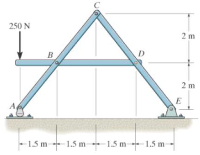
Prob. F6-22
Expert Solution & Answer
Want to see the full answer?
Check out a sample textbook solution
Students have asked these similar questions
Auto Controls
Using MATLAB , find the magnitude and phase plot of the compensators
NO COPIED SOLUTIONS
4-81 The corner shown in Figure P4-81 is initially uniform at 300°C and then suddenly
exposed to a convection environment at 50°C with h 60 W/m². °C. Assume the
=
2
solid has the properties of fireclay brick. Examine nodes 1, 2, 3, 4, and 5 and deter-
mine the maximum time increment which may be used for a transient numerical
calculation.
Figure P4-81
1
2
3
4
1 cm
5
6
1 cm
2 cm
h, T
+
2 cm
Auto Controls
A union feedback control system has the following open loop transfer function
where k>0 is a variable proportional gain
i. for K = 1 , derive the exact magnitude and phase expressions of G(jw).
ii) for K = 1 , identify the gaincross-over frequency (Wgc) [where IG(jo))| 1] and phase cross-overfrequency [where <G(jw) = - 180]. You can use MATLAB command "margin" to obtain there quantities.
iii) Calculate gain margin (in dB) and phase margin (in degrees) ·State whether the closed-loop is stable for K = 1 and briefly justify your answer based on the margin . (Gain marginPhase margin)
iv. what happens to the gain margin and Phase margin when you increase the value of K?you
You can use for loop in MATLAB to check that.Helpful matlab commands : if, bode, margin, rlocus
NO COPIED SOLUTIONS
Chapter 6 Solutions
PEARSON ETEXT ENGINEERING MECH & STATS
Ch. 6 - Determine the force in each member of the truss....Ch. 6 - Determine the force in each member of the truss....Ch. 6 - Determine the force in each member of the truss....Ch. 6 - Determine the greatest load P that can be applied...Ch. 6 - Identify the zero-force members in the truss....Ch. 6 - Determine the force in each member of the truss....Ch. 6 - Determine the force in each member of the truss...Ch. 6 - Determine the force in each member of the truss...Ch. 6 - Determine the force in each member of the truss...Ch. 6 - Determine the force in each member of the truss in...
Ch. 6 - Members AB and BC can each support a maximum...Ch. 6 - Members AB and BC can each support a maximum...Ch. 6 - Determine the force in each member of the truss....Ch. 6 - If the maximum force that any member can support...Ch. 6 - Determine the force in each member of the truss...Ch. 6 - Determine the force in each member of the truss...Ch. 6 - Prob. 22PCh. 6 - Determine the force in members BC, CF, and FE....Ch. 6 - Determine the force in members LK, KC, and CD of...Ch. 6 - Determine the force in members KJ, KD, and CD of...Ch. 6 - Determine the force in members EF, CF, and BC of...Ch. 6 - Determine the force in members DC, HC, and HI of...Ch. 6 - Determine the force in members ED, EH, and GH of...Ch. 6 - Determine the force in members HG, HE and DE of...Ch. 6 - Determine the force in members CD, HI, and CH of...Ch. 6 - Prob. 39PCh. 6 - Determine the force in members CD, CF, and CG and...Ch. 6 - Determine the force developed in members FE, EB,...Ch. 6 - Determine the force in members CD, CJ, GJ, and CG...Ch. 6 - Prob. 48PCh. 6 - Determine the force in members HI, FI, and EF of...Ch. 6 - Determine the force P needed to hold the 60-lb...Ch. 6 - Determine the horizontal and vertical components...Ch. 6 - If a 100-N force is applied to the handles of the...Ch. 6 - Determine the normal force that the 100-lb plate A...Ch. 6 - Determine the force P needed to lift the load....Ch. 6 - Prob. 19FPCh. 6 - Prob. 20FPCh. 6 - Determine the components of reaction at A and C....Ch. 6 - Determine the components of reaction at C. Prob....Ch. 6 - Determine the components of reaction at E. Prob....Ch. 6 - Determine the components of reaction at D and the...Ch. 6 - Determine the force P required to hold the 100-lb...Ch. 6 - Determine the horizontal and vertical components...Ch. 6 - The bridge frame consists of three segments which...Ch. 6 - Determine the reactions at supports A and B. Prob....Ch. 6 - Determine the horizontal and vertical components...Ch. 6 - The compound beam is pin supported at B and...Ch. 6 - When a force of 2 lb is applied to the handles of...Ch. 6 - The hoist supports the 125-kg engine. Determine...Ch. 6 - Prob. 88PCh. 6 - Determine the horizontal and vertical components...Ch. 6 - The pipe cutter is clamped around the pipe P. If...Ch. 6 - Five coins are stacked in the smooth plastic...Ch. 6 - The nail cutter consists of the handle and the two...Ch. 6 - A man having a weight of 175 lb attempts to hold...Ch. 6 - Prob. 97PCh. 6 - If a force of F = 350 N is applied to the handle...Ch. 6 - Prob. 106PCh. 6 - If a force of F = 50 lb is applied to the pads at...Ch. 6 - The spring has an unstretched length of 0.3 m....Ch. 6 - The spring has an unstretched length of 0.3 m....Ch. 6 - The piston C moves vertically between the two...Ch. 6 - Prob. 113PCh. 6 - The platform scale consists of a combination of...Ch. 6 - The three pin-connected members shown in the top...Ch. 6 - Determine the force in each member of the truss...Ch. 6 - Determine the force in each member of the truss...Ch. 6 - Determine the force in member GJ and GC of the...Ch. 6 - Determine the force in members GF, FB, and BC of...Ch. 6 - Determine the horizontal and vertical components...Ch. 6 - Determine the horizontal and vertical components...Ch. 6 - Determine the resultant forces at pins B and C on...
Knowledge Booster


Learn more about
Need a deep-dive on the concept behind this application? Look no further. Learn more about this topic, mechanical-engineering and related others by exploring similar questions and additional content below.Similar questions
- Auto Controls Hand sketch the root Focus of the following transfer function How many asymptotes are there ?what are the angles of the asymptotes?Does the system remain stable for all values of K NO COPIED SOLUTIONSarrow_forward-400" 150" in Datum 80" 90" -280"arrow_forwardUsing hand drawing both of themarrow_forward
- A 10-kg box is pulled along P,Na rough surface by a force P, as shown in thefigure. The pulling force linearly increaseswith time, while the particle is motionless att = 0s untilit reaches a maximum force of100 Nattimet = 4s. If the ground has staticand kinetic friction coefficients of u, = 0.6 andHU, = 0.4 respectively, determine the velocityof the A 1 0 - kg box is pulled along P , N a rough surface by a force P , as shown in the figure. The pulling force linearly increases with time, while the particle is motionless at t = 0 s untilit reaches a maximum force of 1 0 0 Nattimet = 4 s . If the ground has static and kinetic friction coefficients of u , = 0 . 6 and HU , = 0 . 4 respectively, determine the velocity of the particle att = 4 s .arrow_forwardCalculate the speed of the driven member with the following conditions: Diameter of the motor pulley: 4 in Diameter of the driven pulley: 12 in Speed of the motor pulley: 1800 rpmarrow_forward4. In the figure, shaft A made of AISI 1010 hot-rolled steel, is welded to a fixed support and is subjected to loading by equal and opposite Forces F via shaft B. Stress concentration factors K₁ (1.7) and Kts (1.6) are induced by the 3mm fillet. Notch sensitivities are q₁=0.9 and qts=1. The length of shaft A from the fixed support to the connection at shaft B is 1m. The load F cycles from 0.5 to 2kN and a static load P is 100N. For shaft A, find the factor of safety (for infinite life) using the modified Goodman fatigue failure criterion. 3 mm fillet Shaft A 20 mm 25 mm Shaft B 25 mmarrow_forward
arrow_back_ios
SEE MORE QUESTIONS
arrow_forward_ios
Recommended textbooks for you
 International Edition---engineering Mechanics: St...Mechanical EngineeringISBN:9781305501607Author:Andrew Pytel And Jaan KiusalaasPublisher:CENGAGE L
International Edition---engineering Mechanics: St...
Mechanical Engineering
ISBN:9781305501607
Author:Andrew Pytel And Jaan Kiusalaas
Publisher:CENGAGE L
Extent of Reaction; Author: LearnChemE;https://www.youtube.com/watch?v=__stMf3OLP4;License: Standard Youtube License