
PEARSON ETEXT ENGINEERING MECH & STATS
15th Edition
ISBN: 9780137514724
Author: HIBBELER
Publisher: PEARSON
expand_more
expand_more
format_list_bulleted
Videos
Textbook Question
Chapter 6, Problem 3FP
Determine the force in each member of the truss. State if the members are in tension or compression.
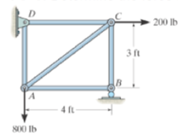
Prob. F6-3
Expert Solution & Answer

Trending nowThis is a popular solution!

Students have asked these similar questions
The net force exerted on the piston by the exploding fuel-air mixture
and friction is 5 kN to the left. A clockwise couple M = 200 N-m acts on the crank AB.
The moment of inertia of the crank about A is 0.0003 kg-m2
. The mass of the
connecting rod BC is 0.36 kg, and its center of mass is 40 mm from B on the line from B
to C. The connecting rod’s moment of inertia about its center of mass is 0.0004 kg-m2
.
The mass of the piston is 4.6 kg. The crank AB has a counterclockwise angular velocity
of 2000 rpm at the instant shown. Neglect the gravitational forces on the crank,
connecting rod, and piston – they still have mass, just don’t include weight on the FBDs.
What is the piston’s acceleration?
Solve only no 1 calculations,the one with diagram,I need handwritten expert solutions
Problem 3
•
Compute the coefficient matrix and the right-hand side of the n-parameter Ritz approximation of the
equation
d
du
(1+x)·
= 0 for 0 < x < 1
dx
dx
u (0)
=
0, u(1) = 1
Use algebraic polynomials for the approximation functions. Specialize your result for n = 2 and compute the
Ritz coefficients.
Chapter 6 Solutions
PEARSON ETEXT ENGINEERING MECH & STATS
Ch. 6 - Determine the force in each member of the truss....Ch. 6 - Determine the force in each member of the truss....Ch. 6 - Determine the force in each member of the truss....Ch. 6 - Determine the greatest load P that can be applied...Ch. 6 - Identify the zero-force members in the truss....Ch. 6 - Determine the force in each member of the truss....Ch. 6 - Determine the force in each member of the truss...Ch. 6 - Determine the force in each member of the truss...Ch. 6 - Determine the force in each member of the truss...Ch. 6 - Determine the force in each member of the truss in...
Ch. 6 - Members AB and BC can each support a maximum...Ch. 6 - Members AB and BC can each support a maximum...Ch. 6 - Determine the force in each member of the truss....Ch. 6 - If the maximum force that any member can support...Ch. 6 - Determine the force in each member of the truss...Ch. 6 - Determine the force in each member of the truss...Ch. 6 - Prob. 22PCh. 6 - Determine the force in members BC, CF, and FE....Ch. 6 - Determine the force in members LK, KC, and CD of...Ch. 6 - Determine the force in members KJ, KD, and CD of...Ch. 6 - Determine the force in members EF, CF, and BC of...Ch. 6 - Determine the force in members DC, HC, and HI of...Ch. 6 - Determine the force in members ED, EH, and GH of...Ch. 6 - Determine the force in members HG, HE and DE of...Ch. 6 - Determine the force in members CD, HI, and CH of...Ch. 6 - Prob. 39PCh. 6 - Determine the force in members CD, CF, and CG and...Ch. 6 - Determine the force developed in members FE, EB,...Ch. 6 - Determine the force in members CD, CJ, GJ, and CG...Ch. 6 - Prob. 48PCh. 6 - Determine the force in members HI, FI, and EF of...Ch. 6 - Determine the force P needed to hold the 60-lb...Ch. 6 - Determine the horizontal and vertical components...Ch. 6 - If a 100-N force is applied to the handles of the...Ch. 6 - Determine the normal force that the 100-lb plate A...Ch. 6 - Determine the force P needed to lift the load....Ch. 6 - Prob. 19FPCh. 6 - Prob. 20FPCh. 6 - Determine the components of reaction at A and C....Ch. 6 - Determine the components of reaction at C. Prob....Ch. 6 - Determine the components of reaction at E. Prob....Ch. 6 - Determine the components of reaction at D and the...Ch. 6 - Determine the force P required to hold the 100-lb...Ch. 6 - Determine the horizontal and vertical components...Ch. 6 - The bridge frame consists of three segments which...Ch. 6 - Determine the reactions at supports A and B. Prob....Ch. 6 - Determine the horizontal and vertical components...Ch. 6 - The compound beam is pin supported at B and...Ch. 6 - When a force of 2 lb is applied to the handles of...Ch. 6 - The hoist supports the 125-kg engine. Determine...Ch. 6 - Prob. 88PCh. 6 - Determine the horizontal and vertical components...Ch. 6 - The pipe cutter is clamped around the pipe P. If...Ch. 6 - Five coins are stacked in the smooth plastic...Ch. 6 - The nail cutter consists of the handle and the two...Ch. 6 - A man having a weight of 175 lb attempts to hold...Ch. 6 - Prob. 97PCh. 6 - If a force of F = 350 N is applied to the handle...Ch. 6 - Prob. 106PCh. 6 - If a force of F = 50 lb is applied to the pads at...Ch. 6 - The spring has an unstretched length of 0.3 m....Ch. 6 - The spring has an unstretched length of 0.3 m....Ch. 6 - The piston C moves vertically between the two...Ch. 6 - Prob. 113PCh. 6 - The platform scale consists of a combination of...Ch. 6 - The three pin-connected members shown in the top...Ch. 6 - Determine the force in each member of the truss...Ch. 6 - Determine the force in each member of the truss...Ch. 6 - Determine the force in member GJ and GC of the...Ch. 6 - Determine the force in members GF, FB, and BC of...Ch. 6 - Determine the horizontal and vertical components...Ch. 6 - Determine the horizontal and vertical components...Ch. 6 - Determine the resultant forces at pins B and C on...
Knowledge Booster


Learn more about
Need a deep-dive on the concept behind this application? Look no further. Learn more about this topic, mechanical-engineering and related others by exploring similar questions and additional content below.Similar questions
- Please measure the size of the following object, and then draw the front, top and side view in the AutoCAD (including the printing) just one arrow for this one 30arrow_forwardQuestion 5 Calculate the Moment about the point B in Nx m B 500 N A 2 m 1.2 m 0.8 m 300 N 7arrow_forwardPlease helparrow_forward
- Question 3 Calculate the Moment about the point B in Nxm A 300 N 2 m 500 N 4 B с 0.8 m 1.2 marrow_forwardSolve this problem and show all of the workarrow_forwardGiven that an L-shaped member (OAB) can rotate about OA, determine the moment vector created by the force about the line OA at the instant shown in the figure below. OA lies in the xy-plane, and the AB part is vertical. Express your answer as a Cartesian vector.arrow_forward
- Determine the magnitude of the moment created by the force about the point A.arrow_forward= MMB 241- Tutorial 1.pdf 2/3 80% + + 10. Determine a ats = 1 m v (m/s) 4 s (m) 2 11. Draw the v-t and s-t graphs if v = 0, s=0 when t=0. a (m/s²) 2 t(s) 12. Draw the v-t graph if v = 0 when t=0. Find the equation v = f(t) for each a (m/s²) 2 segment. 2 -2 13. Determine s and a when t = 3 s if s=0 when t = 0. v (m/s) 2 t(s) t(s) 2arrow_forwardQ.5) A cylinder is supported by spring AD and cables AB and AC as shown. The spring has an at rest length (unstretched length) of 4 meters. If the maximum allowable tension in cables AB and AC is 200 N, determine (a) the largest mass (kg) of cylinder E the system can support, (b) the necessary spring constant (stiffness) to maintain equilibrium, and (b) the tension (magnitude) in each cable when supporting the maximum load found in part (a). B 4 m 3 m A E 1 m 3 m D 5 marrow_forward
arrow_back_ios
SEE MORE QUESTIONS
arrow_forward_ios
Recommended textbooks for you
 Elements Of ElectromagneticsMechanical EngineeringISBN:9780190698614Author:Sadiku, Matthew N. O.Publisher:Oxford University Press
 Mechanics of Materials (10th Edition)Mechanical EngineeringISBN:9780134319650Author:Russell C. HibbelerPublisher:PEARSON
 Thermodynamics: An Engineering ApproachMechanical EngineeringISBN:9781259822674Author:Yunus A. Cengel Dr., Michael A. BolesPublisher:McGraw-Hill Education
 Control Systems EngineeringMechanical EngineeringISBN:9781118170519Author:Norman S. NisePublisher:WILEY
 Mechanics of Materials (MindTap Course List)Mechanical EngineeringISBN:9781337093347Author:Barry J. Goodno, James M. GerePublisher:Cengage Learning
 Engineering Mechanics: StaticsMechanical EngineeringISBN:9781118807330Author:James L. Meriam, L. G. Kraige, J. N. BoltonPublisher:WILEY
Elements Of Electromagnetics
Mechanical Engineering
ISBN:9780190698614
Author:Sadiku, Matthew N. O.
Publisher:Oxford University Press
Mechanics of Materials (10th Edition)
Mechanical Engineering
ISBN:9780134319650
Author:Russell C. Hibbeler
Publisher:PEARSON
Thermodynamics: An Engineering Approach
Mechanical Engineering
ISBN:9781259822674
Author:Yunus A. Cengel Dr., Michael A. Boles
Publisher:McGraw-Hill Education
Control Systems Engineering
Mechanical Engineering
ISBN:9781118170519
Author:Norman S. Nise
Publisher:WILEY
Mechanics of Materials (MindTap Course List)
Mechanical Engineering
ISBN:9781337093347
Author:Barry J. Goodno, James M. Gere
Publisher:Cengage Learning
Engineering Mechanics: Statics
Mechanical Engineering
ISBN:9781118807330
Author:James L. Meriam, L. G. Kraige, J. N. Bolton
Publisher:WILEY
How to balance a see saw using moments example problem; Author: Engineer4Free;https://www.youtube.com/watch?v=d7tX37j-iHU;License: Standard Youtube License