Concept explainers
Using appropriate measurements and data, explain how to determine the bending stress in the blade.
C6–1
Answer to Problem 6.1CP
The bending stress in the blade is
Explanation of Solution
Given information:
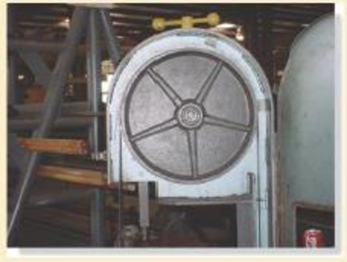
- The steel saw blade passes over the drive wheel of the band saw.
- Use appropriate measurements and data.
Explanation:
The contact area of the cable is upper half portion of the drive wheel. The, the upper half portion of the wheel will undergo stress.
Show the free-body diagram of the drive wheel as in Figure 1.
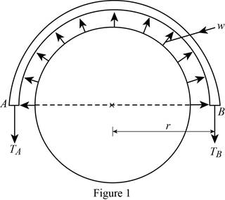
The force induced in the drive wheel will be uniformly distributed.
The circumferential distance of the circular section is
Convert the semi-circular section into beam section as in Figure 2.
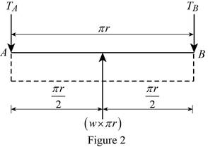
Determine the tension in the cable:
Moment about point A:
Determine the tension in the cable at point B by taking moment about point A.
Along the vertical direction:
Determine the tension in the cable at point A by resolving the vertical component of forces.
Show the calculation of values as follows:
Solve Equation (1).
Substitute
Maximum Bending moment:
The maximum bending moment will occur where the shear force changes sign
Consider a section at a distance x from left end of the beam.
Show the free body diagram of the section as in Figure 3.
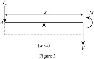
Along the vertical direction:
Determine the shear force at the section by resolving the vertical component of forces.
Moment about the section:
Determine the moment at the section by taking moment about the section.
Substitute 0 for V and
Thus, the maximum bending moment will occur at a distance
Substitute
Bending stress:
Calculate the bending stress in the blade using the flexure formula.
Here, c is the distance between the centroid and the extreme fibre and I is moment of inertia of the band saw.
Consider the band saw is in rectangular cross section.
The value of c is
The moment of inertia of the band saw is
Here, b is width of the section and d is depth of the section.
Substitute
Thus, the bending stress in the blade is
Want to see more full solutions like this?
Chapter 6 Solutions
Mechanics of Materials
- a ship 125m long and 17.5m beam floats in seawater of 1.025 t/m3 at a draught of 8m. the waterplane coefficient is 0.83, block coefficient 0.759 and midship section area coefficient 0.98. calculate i) prismatic coefficient ii) TPC iii) change in mean draught if the vessel moves into water of 1.016 t/m3arrow_forwardc. For the given transfer function, find tp, ts, tr, Mp . Plot the resulting step response. G(s) = 40/(s^2 + 4s + 40) handplot only, and solve for eacharrow_forwardA ship of 9000 tonne displacement floats in fresh water of 1.000 t/m3 at a draught 50 mm below the sea water line. The waterplane area is 1650 m2. Calculate the mass of cargo which must be added so that when entering seawater of 1.025 t/m3 it floats at the seawater line.arrow_forward
- A ship of 15000 tonne displacement floats at a draught of 7 metres in water of 1.000t/cub. Metre.It is required to load the maximum amount of oil to give the ship a draught of 7.0 metre in seawater ofdensity 1.025 t/cub.metre. If the waterplane area is 2150 square metre, calculate the massof oil requiredarrow_forwardA ship of 8000 tonne displacement floats in seawater of 1.025 t/m3 and has a TPC of 14. The vessel moves into fresh water of 1.000 t/m3 and loads 300 tonne of oil fuel. Calculate the change in mean draught.arrow_forwardAuto Controls DONT COPY ANSWERS - will report Perform the partial fraction expansion of the following transfer function and find the impulse response: G(s) = (s/2 + 5/3) / (s^2 + 4s + 6) G(s) =( 6s^2 + 50) / (s+3)(s^2 +4)arrow_forward
- I submitted the below question and received the answer i copied into this question as well. Im unsure if it is correct, so looking for a checkover. i am stuck on the part tan-1 (0.05) = 0.04996 radians. Just unsure where the value for the radians came from. Just need to know how they got that answer and how it is correct before moving on to the next part. If any of the below information is wrong, please feel free to give me a new answer or an entire new explanation. An Inclining experiment done on a ship thats 6500 t, a mass of 30t was moved 6.0 m transvesly causing a 30 cm deflection in a 6m pendulum, calculate the transverse meta centre height. Here is the step-by-step explanation: Given: Displacement of the ship (W) = 6500 tonnes = 6500×1000=6,500,000kg Mass moved transversely (w) = 30 tonnes=30×1000=30,000kg The transverse shift of mass (d) = 6.0 meters Pendulum length (L) = 6.0 meters Pendulum deflection (x) = 30 cm = 0.30 meters Step 1: Formula for Metacentric Height…arrow_forwardAnswer the assignment question, expert onlyarrow_forwardA 1 inch rod diameter B 3/4 inch rod diameter C 1/2 inch rod diameter D 3/8 inch rod diameterarrow_forward
- ANSWER ASAP A Solution A is best B Solution B is best C Solution C is best D Solution D is bestarrow_forwardA distillation column with a total condenser and a partial reboiler is separating ethanol andwater at 1.0 atm. Feed is 0.32 mol fraction ethanol and it enters as a saturated liquid at 100mol/s on the optimum plate. The distillate product is a saturated liquid with 80 mol% ethanol.The condenser removes 5615 kW. The bottoms product is 0.05 mol fraction ethanol. AssumeCMO is valid.(a) Find the number of equilibrium stages for this separation. [6 + PR](b) Find how much larger the actual reflux ratio, R, used is than Rmin, i.e. R/Rmin. [3]Note: the heats of vaporization of ethanol and water are λe = 38.58 and λw = 40.645 arrow_forwardA ship of 7000 tonne displacement has a waterplane areaof 1500 m2. In passing from sea water into river water of1005 kg/m3 there is an increase in draught of 10 cm. Find the Idensity of the sea water. i would like to get the above question sloved in detail. ive attached the picture of the answer from the reeds book. just not sure of all the steps theyve used and the formula in which they started with.arrow_forward
 Elements Of ElectromagneticsMechanical EngineeringISBN:9780190698614Author:Sadiku, Matthew N. O.Publisher:Oxford University Press
 Mechanics of Materials (10th Edition)Mechanical EngineeringISBN:9780134319650Author:Russell C. HibbelerPublisher:PEARSON
 Thermodynamics: An Engineering ApproachMechanical EngineeringISBN:9781259822674Author:Yunus A. Cengel Dr., Michael A. BolesPublisher:McGraw-Hill Education
 Control Systems EngineeringMechanical EngineeringISBN:9781118170519Author:Norman S. NisePublisher:WILEY
 Mechanics of Materials (MindTap Course List)Mechanical EngineeringISBN:9781337093347Author:Barry J. Goodno, James M. GerePublisher:Cengage Learning
 Engineering Mechanics: StaticsMechanical EngineeringISBN:9781118807330Author:James L. Meriam, L. G. Kraige, J. N. BoltonPublisher:WILEY


