
Mechanics of Materials
9th Edition
ISBN: 9780133254426
Author: Russell C. Hibbeler
Publisher: Prentice Hall
expand_more
expand_more
format_list_bulleted
Concept explainers
Videos
Textbook Question
thumb_up100%
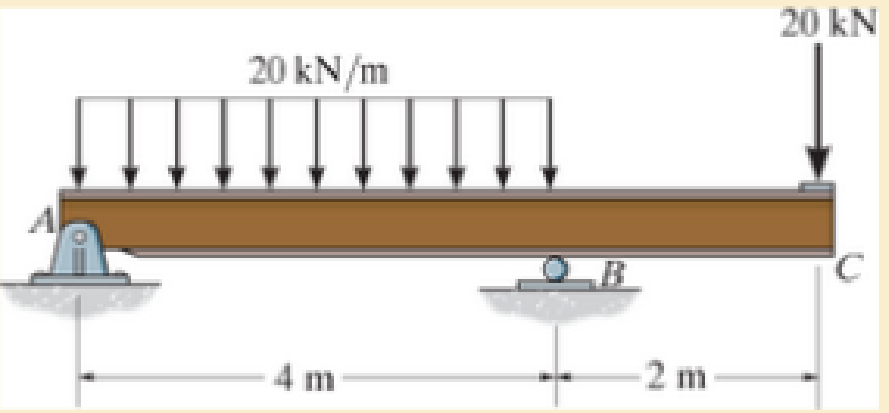
Chapter 6.2, Problem 6.8FP
In each case, draw the shear and moment diagrams for the beam.
Expert Solution & Answer
Want to see the full answer?
Check out a sample textbook solution
Students have asked these similar questions
340 lb
340 lb
Δ
4. In a table of vector differential operators, look up the expressions for V x V in a cylindrical coordinate
system.
(a) Compute the vorticity for the flow in a round tube where the velocity profile is
= vo [1-(³]
V₂ = Vo
(b) Compute the vorticity for an ideal vortex where the velocity is
Ve=
r
where constant.
2πг
(c) Compute the vorticity in the vortex flow given by
Ve=
r
2лг
1- exp
(
r²
4vt
(d) Sketch all the velocity and vorticity profiles.
In the figure, Neglects the heat loss and kinetic and potential energy changes, calculate the work produced by the
turbine in kJ
T = ???
Steam at
P=3 MPa,
T = 280°C
Turbine
Rigid tank
V = 1000 m³
Turbine
Rigid tank
V = 100 m³
V = 1000 m³
V = 100 m³
The valve is
opened.
Initially: evacuated
(empty) tank
O a. 802.8
Initially: Closed valve
O b. 572
O c. 159.93
Od. 415
e. 627.76
equilibrium
Chapter 6 Solutions
Mechanics of Materials
Ch. 6.2 - In each case, the beam is subjected to the...Ch. 6.2 - and then draw the shear and moment diagrams for...Ch. 6.2 - In each case, express the shear and moment...Ch. 6.2 - In each case, express the shear and moment...Ch. 6.2 - In each case, express the shear and moment...Ch. 6.2 - In each case, draw the shear and moment diagrams...Ch. 6.2 - In each case, draw the shear and moment diagrams...Ch. 6.2 - In each case, draw the shear and moment diagrams...Ch. 6.2 - In each case, draw the shear and moment diagrams...Ch. 6.2 - If the force applied to the handle of the load...
Ch. 6.2 - Draw the shear and moment diagrams for the shaft....Ch. 6.2 - The crane is used to support the engine, which has...Ch. 6.2 - Prob. 6.4PCh. 6.2 - •6–5. Draw the shear and moment diagrams for the...Ch. 6.2 - Express the internal shear and moment in terms of...Ch. 6.2 - Prob. 6.7PCh. 6.2 - Prob. 6.8PCh. 6.2 - Prob. 6.9PCh. 6.2 - Members ABC and BD of the counter chair are...Ch. 6.2 - Prob. 6.11PCh. 6.2 - A reinforced concrete pier is used to support the...Ch. 6.2 - Prob. 6.13PCh. 6.2 - The industrial robot is held in the stationary...Ch. 6.2 - Determine the placement distance a of the roller...Ch. 6.2 - Express the internal shear and moment in the...Ch. 6.2 - Draw the shear and moment diagrams for the beam,...Ch. 6.2 - Draw the shear and moment diagrams for the beam....Ch. 6.2 - Draw the shear and moment diagrams for the...Ch. 6.2 - The 150-lb man sits in the center of the boat,...Ch. 6.2 - Prob. 6.22PCh. 6.2 - The footing supports the load transmitted by the...Ch. 6.2 - Express the shear and moment in terms of x for 0 ...Ch. 6.2 - Draw the shear and moment diagrams for the beam...Ch. 6.2 - Draw the shear and moment diagrams for the beam....Ch. 6.2 - Draw the shear and moment diagrams for the beam....Ch. 6.2 - Prob. 6.29PCh. 6.2 - 6–30. The beam is bolted or pinned at A and rests...Ch. 6.2 - The support at A allows the beam to slide freely...Ch. 6.2 - The smooth pin is supported by two leaves A and B...Ch. 6.2 - The shaft is supported by a smooth thrust bearing...Ch. 6.2 - Draw the shear and moment diagrams for the...Ch. 6.2 - Draw the shear and moment diagrams for the beam....Ch. 6.2 - Prob. 6.36PCh. 6.2 - Draw the shear and moment diagrams for the beam...Ch. 6.2 - The beam is used to support a uniform load along...Ch. 6.2 - Draw the shear and moment diagrams for the double...Ch. 6.2 - Draw the shear and moment diagrams for the simply...Ch. 6.2 - The compound beam is fixed at A, pin connected at...Ch. 6.2 - Draw the shear and moment diagrams for the...Ch. 6.2 - The compound beam is fixed at A, pin connected at...Ch. 6.2 - Draw the shear and moment diagrams for the beam....Ch. 6.2 - A short link at B is used to connect beams AB and...Ch. 6.2 - 6–46. Determine the placement b of the hooks to...Ch. 6.4 - Determine the moment of inertia of the cross...Ch. 6.4 - Determine the location of the centroid, y, and the...Ch. 6.4 - In each case, show how the bending stress acts on...Ch. 6.4 - Sketch the bending stress distribution over each...Ch. 6.4 - If the beam is subjected to a bending moment of M...Ch. 6.4 - If the beam is subjected to a bending moment of M...Ch. 6.4 - If the beam is subjected to a bending moment of M...Ch. 6.4 - If the beam is subjected to a bending moment of M...Ch. 6.4 - If the beam is subjected to a bending moment of M...Ch. 6.4 - Prob. 6.47PCh. 6.4 - Determine the moment M that will produce a maximum...Ch. 6.4 - Determine the maximum tensile and compressive...Ch. 6.4 - 6–50. A member has the triangular cross section...Ch. 6.4 - Prob. 6.51PCh. 6.4 - Prob. 6.52PCh. 6.4 - Prob. 6.53PCh. 6.4 - If the built-up beam is subjected to an internal...Ch. 6.4 - If the built-up beam is subjected to an internal...Ch. 6.4 - Prob. 6.56PCh. 6.4 - Prob. 6.57PCh. 6.4 - Prob. 6.58PCh. 6.4 - Prob. 6.59PCh. 6.4 - Prob. 6.60PCh. 6.4 - 6–61. The beam is subjected to a moment of 15 kip...Ch. 6.4 - 6–62. A box beam is constructed from four pieces...Ch. 6.4 - Prob. 6.63PCh. 6.4 - The axle of the freight car is subjected to a...Ch. 6.4 - A shaft is made of a polymer having an elliptical...Ch. 6.4 - Solve Prob. 6-65 if the moment M = 50 N m is...Ch. 6.4 - Prob. 6.67PCh. 6.4 - The shaft is supported by smooth journal bearings...Ch. 6.4 - Prob. 6.69PCh. 6.4 - Prob. 6.70PCh. 6.4 - The boat has a weight of 2300 lb and a center of...Ch. 6.4 - Determine the absolute maximum bending stress in...Ch. 6.4 - Determine the smallest allowable diameter of the...Ch. 6.4 - The pin is used to connect the three links...Ch. 6.4 - The shaft is supported by a thrust bearing at A...Ch. 6.4 - Prob. 6.76PCh. 6.4 - If the beam is subjected to an internal moment of...Ch. 6.4 - If the allowable tensile and compressive stress...Ch. 6.4 - If the beam is subjected to an internal moment of...Ch. 6.4 - If the beam is subjected to a moment of M = 100 kN...Ch. 6.4 - If the beam is made of material having an...Ch. 6.4 - The shaft is supported by a smooth thrust bearing...Ch. 6.4 - The shaft is supported by a thrust bearing at A...Ch. 6.4 - If the intensity of the load w = 15 kN/m,...Ch. 6.4 - If the allowable bending stress is allow = 150...Ch. 6.4 - Prob. 6.86PCh. 6.4 - Prob. 6.87PCh. 6.4 - *6–88. If the beam has a square cross section of 9...Ch. 6.4 - If the compound beam in Prob. 642 has a square...Ch. 6.4 - If the beam in Prob. 628 has a rectangular cross...Ch. 6.4 - Determine the absolute maximum bending stress in...Ch. 6.4 - Determine, to the nearest millimeter, the smallest...Ch. 6.4 - 6–93. The wing spar ABD of a light plane is made...Ch. 6.4 - Prob. 6.94PCh. 6.4 - Prob. 6.95PCh. 6.4 - A log that is 2 ft in diameter is to be cut into a...Ch. 6.4 - A log that is 2 ft in diameter is to be cut into a...Ch. 6.4 - If the beam in Prob.63 has a rectangular cross...Ch. 6.4 - Prob. 6.99PCh. 6.4 - If d = 450 mm, determine the absolute maximum...Ch. 6.4 - If the allowable bending stress is allow = 6 MPa,...Ch. 6.4 - Prob. 6.102PCh. 6.4 - 6–103. If the overhanging beam is made of wood...Ch. 6.5 - Determine the bending stress at corners A and B....Ch. 6.5 - Determine the maximum bending stress in the beams...Ch. 6.5 - The member has a square cross section and is...Ch. 6.5 - The member has a square cross section and is...Ch. 6.5 - Consider the general case of a prismatic beam...Ch. 6.5 - 6–107. If the beam is subjected to the internal...Ch. 6.5 - 6-108. If the wood used for the T-beam has an...Ch. 6.5 - 6-109. The box beam is subjected to the internal...Ch. 6.5 - 6-110. If the wood used for the box beam has an...Ch. 6.5 - 6-111. If the beam is subjected to the internal...Ch. 6.5 - 6-112. If the beam is made from a material having...Ch. 6.5 - Prob. 6.113PCh. 6.5 - 6-114. The T-beam is subjected to a bending moment...Ch. 6.5 - 6-115. The beam has a rectangular cross section....Ch. 6.5 - For the section, Iy' = 31.7(10-6) m4, Iz' =...Ch. 6.5 - For the section, Iy' = 31.7(10-6) m4, Iz' =...Ch. 6.5 - If the applied distributed loading of w = 4 kN/m...Ch. 6.5 - Determine the maximum allowable intensity w of the...Ch. 6.9 - The composite beam is made of steel (A) bonded to...Ch. 6.9 - The composite beam is made of steel (A) bonded to...Ch. 6.9 - Segment A of the composite beam is made from...Ch. 6.9 - Segment A of the composite beam is made from...Ch. 6.9 - Prob. 6.124PCh. 6.9 - The wooden section of the beam is reinforced with...Ch. 6.9 - The wooden section of the beam is reinforced with...Ch. 6.9 - Prob. 6.127PCh. 6.9 - The steel channel is used to reinforce the wood...Ch. 6.9 - Prob. 6.129PCh. 6.9 - 6-130. The beam is made from three types of...Ch. 6.9 - 6-131. The concrete beam is reinforced with three...Ch. 6.9 - *6-132. The wide-flange section is reinforced with...Ch. 6.9 - Prob. 6.133PCh. 6.9 - If the beam is subjected to a moment of M = 45 kN...Ch. 6.9 - Prob. 6.135PCh. 6.9 - For the curved beam in Fig. 640a, show that when...Ch. 6.9 - The curved member is subjected to the moment of M...Ch. 6.9 - The curved member is made from material having an...Ch. 6.9 - The curved beam is subjected to a moment of M = 40...Ch. 6.9 - The curved beam is made from material having an...Ch. 6.9 - If P = 3 kN, determine the bending stress at...Ch. 6.9 - If the maximum bending stress at section a-a is...Ch. 6.9 - The elbow of the pipe has an outer radius of 0.75...Ch. 6.9 - Prob. 6.144PCh. 6.9 - Prob. 6.145PCh. 6.9 - Prob. 6.146PCh. 6.9 - Prob. 6.147PCh. 6.9 - Prob. 6.148PCh. 6.9 - Prob. 6.149PCh. 6.9 - 6-150. The bar is subjected to a moment of M = 153...Ch. 6.9 - Prob. 6.151PCh. 6.9 - Prob. 6.152PCh. 6.9 - Prob. 6.153PCh. 6.9 - 6-154. The simply supported notched bar is...Ch. 6.9 - Prob. 6.155PCh. 6.9 - *6-156. Determine the length L of the center...Ch. 6.9 - Prob. 6.157PCh. 6.10 - Determine the shape factor for the wide-flange...Ch. 6.10 - 6-159. The beam is made of an elastic plastic...Ch. 6.10 - Prob. 6.160PCh. 6.10 - Prob. 6.161PCh. 6.10 - Prob. 6.162PCh. 6.10 - Determine the plastic moment Mp that can be...Ch. 6.10 - Determine the shape factor for the beam. Prob....Ch. 6.10 - The beam is made of elastic perfectly plastic...Ch. 6.10 - Determine the shape factor for the beam. Prob....Ch. 6.10 - The beam is made of an elastic perfectly plastic...Ch. 6.10 - Prob. 6.168PCh. 6.10 - Prob. 6.169PCh. 6.10 - 6-170. The box beam is made from an...Ch. 6.10 - 6-171. The beam is made from elastic-perfectly...Ch. 6.10 - *6-172. Determine the shape factor for the...Ch. 6.10 - Prob. 6.173PCh. 6.10 - Prob. 6.174PCh. 6.10 - 6-175. The box beam is made from an...Ch. 6.10 - The wide-flange member is made from an elastic...Ch. 6.10 - Prob. 6.177PCh. 6.10 - The plexiglass bar has a stress-strain curve that...Ch. 6.10 - The stress-strain diagram for a titanium alloy can...Ch. 6.10 - A beam is made from polypropylene plastic and has...Ch. 6.10 - Prob. 6.181PCh. 6.10 - The bar is made of an aluminum alloy having a...Ch. 6 - Using appropriate measurements and data, explain...Ch. 6 - Determine the shape factor for the wide-flange...Ch. 6 - Prob. 6.184RPCh. 6 - The compound beam consists of two segments that...Ch. 6 - The composite beam consists of a wood core and two...Ch. 6 - 6-187. Solve Prob. 6-186 if the moment is applied...Ch. 6 - If it resists a moment of M = 125 N m, determine...Ch. 6 - Determine the maximum bending stress in the handle...Ch. 6 - The curved beam is subjected to a bending moment...Ch. 6 - Determine the shear and moment in the beam as...Ch. 6 - A wooden beam has a square cross section as shown...Ch. 6 - Draw the shear and moment diagrams for the shaft...Ch. 6 - The strut has a square cross section a by a and is...
Knowledge Booster


Learn more about
Need a deep-dive on the concept behind this application? Look no further. Learn more about this topic, mechanical-engineering and related others by exploring similar questions and additional content below.Similar questions
- Please find the torsional yield strength, the yield strength, the spring index, and the mean diameter. Use: E = 28.6 Mpsi, G = 11.5 Mpsi, A = 140 kpsi·in, m = 0.190, and relative cost= 1.arrow_forwardA viscoelastic column is made of a material with a creep compliance of D(t)= 0.75+0.5log10t+0.18(log10t)^2 GPA^-1 for t in s. If a constant compressive stress of σ0 = –100 MPa is applied at t = 0, how long will it take (= t1/2) for the height of the column to decrease to ½ its original value? Note: You will obtain multiple answers for this problem! One makes sense physically and one does not.arrow_forwardA group of 23 power transistors, dissipating 2 W each, are to be cooled by attaching them to a black-anodized square aluminum plate and mounting the plate on the wall of a room at 30°C. The emissivity of the transistor and the plate surfaces is 0.9. Assuming the heat transfer from the back side of the plate to be negligible and the temperature of the surrounding surfaces to be the same as the air temperature of the room, determine the length of the square plate if the average surface temperature of the plate is not to exceed 50°C. Start the iteration process with an initial guess of the size of the plate as 43 cm. The properties of air at 1 atm and the film temperature of (Ts + T)/2 = (50 + 30)/2 = 40°C are k = 0.02662 W/m·°C, ν = 1.702 × 10⁻⁵ m2 /s, Pr = 0.7255, and β = 0.003195 K–1. Multiple Choice 0.473 m 0.284 m 0.513 m 0.671 marrow_forward
- A 40-cm-diameter, 127-cm-high cylindrical hot water tank is located in the bathroom of a house maintained at 20°C. The surface temperature of the tank is measured to be 44°C and its emissivity is 0.4. Taking the surrounding surface temperature to be also 20°C, determine the rate of heat loss from all surfaces of the tank by natural convection and radiation. The properties of air at 32°C are k=0.02603 W/m-K, v=1.627 x 10⁻⁵ m²/s, Pr = 0.7276, and ẞ = 0.003279 K-1 The rate of heat loss from all surfaces of the tank by natural convection is The rate of heat loss from all surfaces of the tank by radiation is W. W.arrow_forwardA 2.5-m-long thin vertical plate is subjected to uniform heat flux on one side, while the other side is exposed to cool air at 5°C. The plate surface has an emissivity of 0.73, and its midpoint temperature is 55°C. Determine the heat flux subjected on the plate surface. Uniform heat flux -Plate, € = 0.73 Cool air 5°C 7 TSUIT Given: The properties of water at Tf,c= 30°C. k=0.02588 W/m.K, v=1.608 x 10⁻⁵ m²/s Pr = 0.7282 The heat flux subjected on the plate surface is W/m²arrow_forwardHot water is flowing at an average velocity of 5.82 ft/s through a cast iron pipe (k=30 Btu/h-ft-°F) whose inner and outer diameters are 1.0 in and 1.2 in, respectively. The pipe passes through a 50-ft-long section of a basement whose temperature is 60°F. The emissivity of the outer surface of the pipe is 0.5, and the walls of the basement are also at about 60°F. If the inlet temperature of the water is 150°F and the heat transfer coefficient on the inner surface of the pipe is 30 Btu/h-ft².°F, determine the temperature drop of water as it passes through the basement. Evaluate air properties at a film temperature of 105°C and 1 atm pressure. The properties of air at 1 atm and the film temperature of (Ts+ T∞)/2 = (150+60)/2 = 105°F are k=0.01541 Btu/h-ft-°F. v=0.1838 × 10⁻³ ft2/s, Pr = 0.7253, and ẞ = 0.00177R-1arrow_forward
- hand-written solutions only, please. correct answers upvoted!arrow_forwardhand-written solutions only, please. correct answers upvoted!arrow_forward! Required information Consider a flat-plate solar collector placed horizontally on the flat roof of a house. The collector is 1.3 m wide and 2.8 m long, and the average temperature of the exposed surface of the collector is 42°C. The properties of air at 1 atm and the film temperature are k=0.02551 W/m-°C, v = 1.562 × 10⁻⁵ m²/s, Pr = 0.7286, and ẞ= 0.003356 K-1 Determine the rate of heat loss from the collector by natural convection during a calm day when the ambient air temperature is 8°C. The rate of heat loss from the collector by natural convection is W.arrow_forward
arrow_back_ios
SEE MORE QUESTIONS
arrow_forward_ios
Recommended textbooks for you
 Elements Of ElectromagneticsMechanical EngineeringISBN:9780190698614Author:Sadiku, Matthew N. O.Publisher:Oxford University Press
 Mechanics of Materials (10th Edition)Mechanical EngineeringISBN:9780134319650Author:Russell C. HibbelerPublisher:PEARSON
 Thermodynamics: An Engineering ApproachMechanical EngineeringISBN:9781259822674Author:Yunus A. Cengel Dr., Michael A. BolesPublisher:McGraw-Hill Education
 Control Systems EngineeringMechanical EngineeringISBN:9781118170519Author:Norman S. NisePublisher:WILEY
 Mechanics of Materials (MindTap Course List)Mechanical EngineeringISBN:9781337093347Author:Barry J. Goodno, James M. GerePublisher:Cengage Learning
 Engineering Mechanics: StaticsMechanical EngineeringISBN:9781118807330Author:James L. Meriam, L. G. Kraige, J. N. BoltonPublisher:WILEY
Elements Of Electromagnetics
Mechanical Engineering
ISBN:9780190698614
Author:Sadiku, Matthew N. O.
Publisher:Oxford University Press
Mechanics of Materials (10th Edition)
Mechanical Engineering
ISBN:9780134319650
Author:Russell C. Hibbeler
Publisher:PEARSON
Thermodynamics: An Engineering Approach
Mechanical Engineering
ISBN:9781259822674
Author:Yunus A. Cengel Dr., Michael A. Boles
Publisher:McGraw-Hill Education
Control Systems Engineering
Mechanical Engineering
ISBN:9781118170519
Author:Norman S. Nise
Publisher:WILEY
Mechanics of Materials (MindTap Course List)
Mechanical Engineering
ISBN:9781337093347
Author:Barry J. Goodno, James M. Gere
Publisher:Cengage Learning
Engineering Mechanics: Statics
Mechanical Engineering
ISBN:9781118807330
Author:James L. Meriam, L. G. Kraige, J. N. Bolton
Publisher:WILEY
Understanding Shear Force and Bending Moment Diagrams; Author: The Efficient Engineer;https://www.youtube.com/watch?v=C-FEVzI8oe8;License: Standard YouTube License, CC-BY
Bending Stress; Author: moodlemech;https://www.youtube.com/watch?v=9QIqewkE6xM;License: Standard Youtube License