
Mechanics of Materials
9th Edition
ISBN: 9780133254426
Author: Russell C. Hibbeler
Publisher: Prentice Hall
expand_more
expand_more
format_list_bulleted
Concept explainers
Videos
Textbook Question
Chapter 6.10, Problem 6.179P
The stress-strain diagram for a titanium alloy can be approximated by the two straight lines. If a strut made of this material is subjected to bending, determine the moment resisted by the strut if the maximum stress reaches a value of (a) σA and (b) σB.
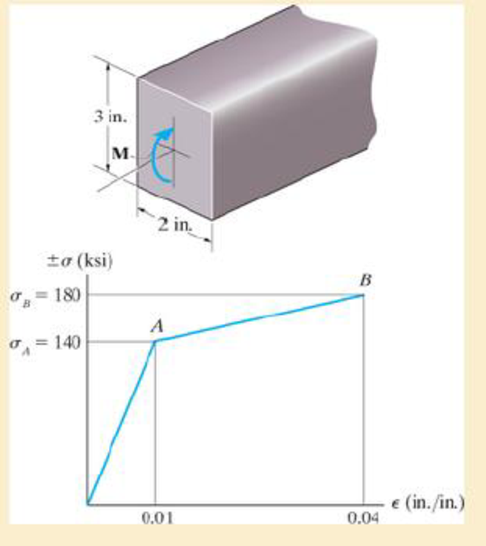
Prob. 6–179
Expert Solution & Answer
Want to see the full answer?
Check out a sample textbook solution
Students have asked these similar questions
500
Q3: The attachment shown in Fig.3 is made of
1040 HR. The static force is 30 kN. Specify the
weldment (give the pattern, electrode
number, type of weld, length of weld, and leg
size).
Fig. 3
All dimension
in mm
30 kN
100
(10 Marks)
(read image) (answer given)
A cylinder and a disk are used as pulleys, as shown in the figure. Using the data
given in the figure, if a body of mass m = 3 kg is released from rest after falling a
height h 1.5 m, find:
a) The velocity of the body.
b) The angular velocity of the disk.
c) The number of revolutions the cylinder has made.
T₁
F
Rd =
0.2 m
md =
2 kg
T
T₂1
Rc = 0.4 m
mc = 5 kg
☐ m = 3 kg
Chapter 6 Solutions
Mechanics of Materials
Ch. 6.2 - In each case, the beam is subjected to the...Ch. 6.2 - and then draw the shear and moment diagrams for...Ch. 6.2 - In each case, express the shear and moment...Ch. 6.2 - In each case, express the shear and moment...Ch. 6.2 - In each case, express the shear and moment...Ch. 6.2 - In each case, draw the shear and moment diagrams...Ch. 6.2 - In each case, draw the shear and moment diagrams...Ch. 6.2 - In each case, draw the shear and moment diagrams...Ch. 6.2 - In each case, draw the shear and moment diagrams...Ch. 6.2 - If the force applied to the handle of the load...
Ch. 6.2 - Draw the shear and moment diagrams for the shaft....Ch. 6.2 - The crane is used to support the engine, which has...Ch. 6.2 - Prob. 6.4PCh. 6.2 - •6–5. Draw the shear and moment diagrams for the...Ch. 6.2 - Express the internal shear and moment in terms of...Ch. 6.2 - Prob. 6.7PCh. 6.2 - Prob. 6.8PCh. 6.2 - Prob. 6.9PCh. 6.2 - Members ABC and BD of the counter chair are...Ch. 6.2 - Prob. 6.11PCh. 6.2 - A reinforced concrete pier is used to support the...Ch. 6.2 - Prob. 6.13PCh. 6.2 - The industrial robot is held in the stationary...Ch. 6.2 - Determine the placement distance a of the roller...Ch. 6.2 - Express the internal shear and moment in the...Ch. 6.2 - Draw the shear and moment diagrams for the beam,...Ch. 6.2 - Draw the shear and moment diagrams for the beam....Ch. 6.2 - Draw the shear and moment diagrams for the...Ch. 6.2 - The 150-lb man sits in the center of the boat,...Ch. 6.2 - Prob. 6.22PCh. 6.2 - The footing supports the load transmitted by the...Ch. 6.2 - Express the shear and moment in terms of x for 0 ...Ch. 6.2 - Draw the shear and moment diagrams for the beam...Ch. 6.2 - Draw the shear and moment diagrams for the beam....Ch. 6.2 - Draw the shear and moment diagrams for the beam....Ch. 6.2 - Prob. 6.29PCh. 6.2 - 6–30. The beam is bolted or pinned at A and rests...Ch. 6.2 - The support at A allows the beam to slide freely...Ch. 6.2 - The smooth pin is supported by two leaves A and B...Ch. 6.2 - The shaft is supported by a smooth thrust bearing...Ch. 6.2 - Draw the shear and moment diagrams for the...Ch. 6.2 - Draw the shear and moment diagrams for the beam....Ch. 6.2 - Prob. 6.36PCh. 6.2 - Draw the shear and moment diagrams for the beam...Ch. 6.2 - The beam is used to support a uniform load along...Ch. 6.2 - Draw the shear and moment diagrams for the double...Ch. 6.2 - Draw the shear and moment diagrams for the simply...Ch. 6.2 - The compound beam is fixed at A, pin connected at...Ch. 6.2 - Draw the shear and moment diagrams for the...Ch. 6.2 - The compound beam is fixed at A, pin connected at...Ch. 6.2 - Draw the shear and moment diagrams for the beam....Ch. 6.2 - A short link at B is used to connect beams AB and...Ch. 6.2 - 6–46. Determine the placement b of the hooks to...Ch. 6.4 - Determine the moment of inertia of the cross...Ch. 6.4 - Determine the location of the centroid, y, and the...Ch. 6.4 - In each case, show how the bending stress acts on...Ch. 6.4 - Sketch the bending stress distribution over each...Ch. 6.4 - If the beam is subjected to a bending moment of M...Ch. 6.4 - If the beam is subjected to a bending moment of M...Ch. 6.4 - If the beam is subjected to a bending moment of M...Ch. 6.4 - If the beam is subjected to a bending moment of M...Ch. 6.4 - If the beam is subjected to a bending moment of M...Ch. 6.4 - Prob. 6.47PCh. 6.4 - Determine the moment M that will produce a maximum...Ch. 6.4 - Determine the maximum tensile and compressive...Ch. 6.4 - 6–50. A member has the triangular cross section...Ch. 6.4 - Prob. 6.51PCh. 6.4 - Prob. 6.52PCh. 6.4 - Prob. 6.53PCh. 6.4 - If the built-up beam is subjected to an internal...Ch. 6.4 - If the built-up beam is subjected to an internal...Ch. 6.4 - Prob. 6.56PCh. 6.4 - Prob. 6.57PCh. 6.4 - Prob. 6.58PCh. 6.4 - Prob. 6.59PCh. 6.4 - Prob. 6.60PCh. 6.4 - 6–61. The beam is subjected to a moment of 15 kip...Ch. 6.4 - 6–62. A box beam is constructed from four pieces...Ch. 6.4 - Prob. 6.63PCh. 6.4 - The axle of the freight car is subjected to a...Ch. 6.4 - A shaft is made of a polymer having an elliptical...Ch. 6.4 - Solve Prob. 6-65 if the moment M = 50 N m is...Ch. 6.4 - Prob. 6.67PCh. 6.4 - The shaft is supported by smooth journal bearings...Ch. 6.4 - Prob. 6.69PCh. 6.4 - Prob. 6.70PCh. 6.4 - The boat has a weight of 2300 lb and a center of...Ch. 6.4 - Determine the absolute maximum bending stress in...Ch. 6.4 - Determine the smallest allowable diameter of the...Ch. 6.4 - The pin is used to connect the three links...Ch. 6.4 - The shaft is supported by a thrust bearing at A...Ch. 6.4 - Prob. 6.76PCh. 6.4 - If the beam is subjected to an internal moment of...Ch. 6.4 - If the allowable tensile and compressive stress...Ch. 6.4 - If the beam is subjected to an internal moment of...Ch. 6.4 - If the beam is subjected to a moment of M = 100 kN...Ch. 6.4 - If the beam is made of material having an...Ch. 6.4 - The shaft is supported by a smooth thrust bearing...Ch. 6.4 - The shaft is supported by a thrust bearing at A...Ch. 6.4 - If the intensity of the load w = 15 kN/m,...Ch. 6.4 - If the allowable bending stress is allow = 150...Ch. 6.4 - Prob. 6.86PCh. 6.4 - Prob. 6.87PCh. 6.4 - *6–88. If the beam has a square cross section of 9...Ch. 6.4 - If the compound beam in Prob. 642 has a square...Ch. 6.4 - If the beam in Prob. 628 has a rectangular cross...Ch. 6.4 - Determine the absolute maximum bending stress in...Ch. 6.4 - Determine, to the nearest millimeter, the smallest...Ch. 6.4 - 6–93. The wing spar ABD of a light plane is made...Ch. 6.4 - Prob. 6.94PCh. 6.4 - Prob. 6.95PCh. 6.4 - A log that is 2 ft in diameter is to be cut into a...Ch. 6.4 - A log that is 2 ft in diameter is to be cut into a...Ch. 6.4 - If the beam in Prob.63 has a rectangular cross...Ch. 6.4 - Prob. 6.99PCh. 6.4 - If d = 450 mm, determine the absolute maximum...Ch. 6.4 - If the allowable bending stress is allow = 6 MPa,...Ch. 6.4 - Prob. 6.102PCh. 6.4 - 6–103. If the overhanging beam is made of wood...Ch. 6.5 - Determine the bending stress at corners A and B....Ch. 6.5 - Determine the maximum bending stress in the beams...Ch. 6.5 - The member has a square cross section and is...Ch. 6.5 - The member has a square cross section and is...Ch. 6.5 - Consider the general case of a prismatic beam...Ch. 6.5 - 6–107. If the beam is subjected to the internal...Ch. 6.5 - 6-108. If the wood used for the T-beam has an...Ch. 6.5 - 6-109. The box beam is subjected to the internal...Ch. 6.5 - 6-110. If the wood used for the box beam has an...Ch. 6.5 - 6-111. If the beam is subjected to the internal...Ch. 6.5 - 6-112. If the beam is made from a material having...Ch. 6.5 - Prob. 6.113PCh. 6.5 - 6-114. The T-beam is subjected to a bending moment...Ch. 6.5 - 6-115. The beam has a rectangular cross section....Ch. 6.5 - For the section, Iy' = 31.7(10-6) m4, Iz' =...Ch. 6.5 - For the section, Iy' = 31.7(10-6) m4, Iz' =...Ch. 6.5 - If the applied distributed loading of w = 4 kN/m...Ch. 6.5 - Determine the maximum allowable intensity w of the...Ch. 6.9 - The composite beam is made of steel (A) bonded to...Ch. 6.9 - The composite beam is made of steel (A) bonded to...Ch. 6.9 - Segment A of the composite beam is made from...Ch. 6.9 - Segment A of the composite beam is made from...Ch. 6.9 - Prob. 6.124PCh. 6.9 - The wooden section of the beam is reinforced with...Ch. 6.9 - The wooden section of the beam is reinforced with...Ch. 6.9 - Prob. 6.127PCh. 6.9 - The steel channel is used to reinforce the wood...Ch. 6.9 - Prob. 6.129PCh. 6.9 - 6-130. The beam is made from three types of...Ch. 6.9 - 6-131. The concrete beam is reinforced with three...Ch. 6.9 - *6-132. The wide-flange section is reinforced with...Ch. 6.9 - Prob. 6.133PCh. 6.9 - If the beam is subjected to a moment of M = 45 kN...Ch. 6.9 - Prob. 6.135PCh. 6.9 - For the curved beam in Fig. 640a, show that when...Ch. 6.9 - The curved member is subjected to the moment of M...Ch. 6.9 - The curved member is made from material having an...Ch. 6.9 - The curved beam is subjected to a moment of M = 40...Ch. 6.9 - The curved beam is made from material having an...Ch. 6.9 - If P = 3 kN, determine the bending stress at...Ch. 6.9 - If the maximum bending stress at section a-a is...Ch. 6.9 - The elbow of the pipe has an outer radius of 0.75...Ch. 6.9 - Prob. 6.144PCh. 6.9 - Prob. 6.145PCh. 6.9 - Prob. 6.146PCh. 6.9 - Prob. 6.147PCh. 6.9 - Prob. 6.148PCh. 6.9 - Prob. 6.149PCh. 6.9 - 6-150. The bar is subjected to a moment of M = 153...Ch. 6.9 - Prob. 6.151PCh. 6.9 - Prob. 6.152PCh. 6.9 - Prob. 6.153PCh. 6.9 - 6-154. The simply supported notched bar is...Ch. 6.9 - Prob. 6.155PCh. 6.9 - *6-156. Determine the length L of the center...Ch. 6.9 - Prob. 6.157PCh. 6.10 - Determine the shape factor for the wide-flange...Ch. 6.10 - 6-159. The beam is made of an elastic plastic...Ch. 6.10 - Prob. 6.160PCh. 6.10 - Prob. 6.161PCh. 6.10 - Prob. 6.162PCh. 6.10 - Determine the plastic moment Mp that can be...Ch. 6.10 - Determine the shape factor for the beam. Prob....Ch. 6.10 - The beam is made of elastic perfectly plastic...Ch. 6.10 - Determine the shape factor for the beam. Prob....Ch. 6.10 - The beam is made of an elastic perfectly plastic...Ch. 6.10 - Prob. 6.168PCh. 6.10 - Prob. 6.169PCh. 6.10 - 6-170. The box beam is made from an...Ch. 6.10 - 6-171. The beam is made from elastic-perfectly...Ch. 6.10 - *6-172. Determine the shape factor for the...Ch. 6.10 - Prob. 6.173PCh. 6.10 - Prob. 6.174PCh. 6.10 - 6-175. The box beam is made from an...Ch. 6.10 - The wide-flange member is made from an elastic...Ch. 6.10 - Prob. 6.177PCh. 6.10 - The plexiglass bar has a stress-strain curve that...Ch. 6.10 - The stress-strain diagram for a titanium alloy can...Ch. 6.10 - A beam is made from polypropylene plastic and has...Ch. 6.10 - Prob. 6.181PCh. 6.10 - The bar is made of an aluminum alloy having a...Ch. 6 - Using appropriate measurements and data, explain...Ch. 6 - Determine the shape factor for the wide-flange...Ch. 6 - Prob. 6.184RPCh. 6 - The compound beam consists of two segments that...Ch. 6 - The composite beam consists of a wood core and two...Ch. 6 - 6-187. Solve Prob. 6-186 if the moment is applied...Ch. 6 - If it resists a moment of M = 125 N m, determine...Ch. 6 - Determine the maximum bending stress in the handle...Ch. 6 - The curved beam is subjected to a bending moment...Ch. 6 - Determine the shear and moment in the beam as...Ch. 6 - A wooden beam has a square cross section as shown...Ch. 6 - Draw the shear and moment diagrams for the shaft...Ch. 6 - The strut has a square cross section a by a and is...
Knowledge Booster


Learn more about
Need a deep-dive on the concept behind this application? Look no further. Learn more about this topic, mechanical-engineering and related others by exploring similar questions and additional content below.Similar questions
- (read image) (answer given)arrow_forward11-5. Compute all the dimensional changes for the steel bar when subjected to the loads shown. The proportional limit of the steel is 230 MPa. 265 kN 100 mm 600 kN 25 mm thickness X Z 600 kN 450 mm E=207×103 MPa; μ= 0.25 265 kNarrow_forwardT₁ F Rd = 0.2 m md = 2 kg T₂ Tz1 Rc = 0.4 m mc = 5 kg m = 3 kgarrow_forward
- 2. Find a basis of solutions by the Frobenius method. Try to identify the series as expansions of known functions. (x + 2)²y" + (x + 2)y' - y = 0 ; Hint: Let: z = x+2arrow_forward1. Find a power series solution in powers of x. y" - y' + x²y = 0arrow_forward3. Find a basis of solutions by the Frobenius method. Try to identify the series as expansions of known functions. 8x2y" +10xy' + (x 1)y = 0 -arrow_forward
- Hello I was going over the solution for this probem and I'm a bit confused on the last part. Can you please explain to me 1^4 was used for the Co of the tubular cross section? Thank you!arrow_forwardBlood (HD = 0.45 in large diameter tubes) is forced through hollow fiber tubes that are 20 µm in diameter.Equating the volumetric flowrate expressions from (1) assuming marginal zone theory and (2) using an apparentviscosity for the blood, estimate the marginal zone thickness at this diameter. The viscosity of plasma is 1.2 cParrow_forwardQ2: Find the shear load on bolt A for the connection shown in Figure 2. Dimensions are in mm Fig. 2 24 0-0 0-0 A 180kN (10 Markarrow_forward
- determine the direction and magnitude of angular velocity ω3 of link CD in the four-bar linkage using the relative velocity graphical methodarrow_forwardFour-bar linkage mechanism, AB=40mm, BC=60mm, CD=70mm, AD=80mm, =60°, w1=10rad/s. Determine the direction and magnitude of w3 using relative motion graphical method. A B 2 3 77777 477777arrow_forwardFour-bar linkage mechanism, AB=40mm, BC=60mm, CD=70mm, AD=80mm, =60°, w1=10rad/s. Determine the direction and magnitude of w3 using relative motion graphical method. A B 2 3 77777 477777arrow_forward
arrow_back_ios
SEE MORE QUESTIONS
arrow_forward_ios
Recommended textbooks for you
 Elements Of ElectromagneticsMechanical EngineeringISBN:9780190698614Author:Sadiku, Matthew N. O.Publisher:Oxford University Press
 Mechanics of Materials (10th Edition)Mechanical EngineeringISBN:9780134319650Author:Russell C. HibbelerPublisher:PEARSON
 Thermodynamics: An Engineering ApproachMechanical EngineeringISBN:9781259822674Author:Yunus A. Cengel Dr., Michael A. BolesPublisher:McGraw-Hill Education
 Control Systems EngineeringMechanical EngineeringISBN:9781118170519Author:Norman S. NisePublisher:WILEY
 Mechanics of Materials (MindTap Course List)Mechanical EngineeringISBN:9781337093347Author:Barry J. Goodno, James M. GerePublisher:Cengage Learning
 Engineering Mechanics: StaticsMechanical EngineeringISBN:9781118807330Author:James L. Meriam, L. G. Kraige, J. N. BoltonPublisher:WILEY
Elements Of Electromagnetics
Mechanical Engineering
ISBN:9780190698614
Author:Sadiku, Matthew N. O.
Publisher:Oxford University Press
Mechanics of Materials (10th Edition)
Mechanical Engineering
ISBN:9780134319650
Author:Russell C. Hibbeler
Publisher:PEARSON
Thermodynamics: An Engineering Approach
Mechanical Engineering
ISBN:9781259822674
Author:Yunus A. Cengel Dr., Michael A. Boles
Publisher:McGraw-Hill Education
Control Systems Engineering
Mechanical Engineering
ISBN:9781118170519
Author:Norman S. Nise
Publisher:WILEY
Mechanics of Materials (MindTap Course List)
Mechanical Engineering
ISBN:9781337093347
Author:Barry J. Goodno, James M. Gere
Publisher:Cengage Learning
Engineering Mechanics: Statics
Mechanical Engineering
ISBN:9781118807330
Author:James L. Meriam, L. G. Kraige, J. N. Bolton
Publisher:WILEY
Stresses Due to Fluctuating Loads Introduction - Design Against Fluctuating Loads - Machine Design 1; Author: Ekeeda;https://www.youtube.com/watch?v=3FBmQXfP_eE;License: Standard Youtube License