
Shigley's Mechanical Engineering Design (McGraw-Hill Series in Mechanical Engineering)
10th Edition
ISBN: 9780073398204
Author: Richard G Budynas, Keith J Nisbett
Publisher: McGraw-Hill Education
expand_more
expand_more
format_list_bulleted
Concept explainers
Videos
Textbook Question
Chapter 6, Problem 51P
6-51* to 6-53* For the problem specified in the table, build upon the results of the original problem to deter-mine the minimum factor of safety for fatigue at point A, based on infinite life, using the modified Goodman criterion. If the life is not infinite, estimate the number of cycles. The force F is applied as a repeated load. The material is AISI 1018 CD steel.
| Problem Number | Original Problem, Page Number |
| 6-51* | 3-84, 154 |
3-84* The cantilevered bar in the figure is made from a ductile material and is statically loaded with Fy = 250 Ibf and Fx = Fz = 0. Analyze the stress situation in the small diameter at the shoulder at A by obtaining the following information.
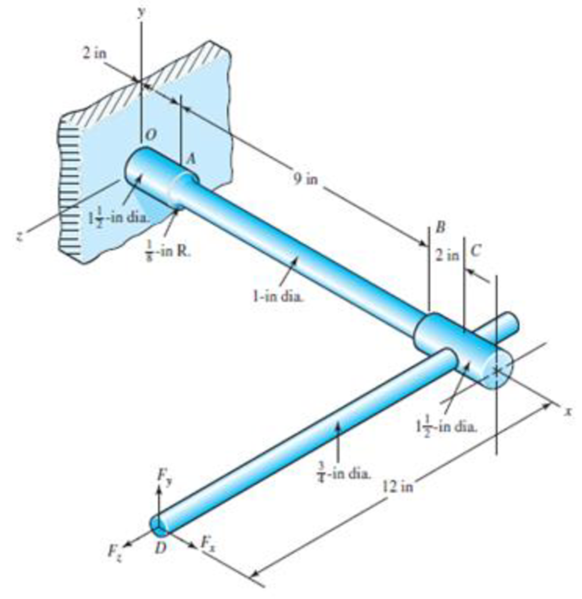
- (a) Determine the precise location of the critical stress element at the cross section at A.
- (b) Sketch the critical stress clement and determine magnitudes and directions for all stresses acting on it. (Transverse shear may be neglected if you can justify this decision.)
- (c) For the critical stress clement, determine the principal stresses and the maximum shear stress.
Expert Solution & Answer
Want to see the full answer?
Check out a sample textbook solution
Students have asked these similar questions
=
The steel curved bar shown has rectangular cross-section with a radial height h = 6 mm and thickness b = 4mm. The
radius of the centroidal axis is R = 80 mm. A force P = 10 N is applied as shown. Assume the steel modulus of
207,000 MPa and G = 79.3(103) MPa, repectively.
elasticity and shear modulus E =
Find the vertical deflection at point B. Use Castigliano's method for a curved flexural member and since R/h > 10,
neglect the effect of shear and axial load, thereby assuming that deflection is due to merely the bending moment.
Note the inner and outer radii of the curves bar are:
r = 80 + ½ (6) = 83 mm, r₁ = 80 − ½ (6) = 77 mm
2
2
Sπ/2 sin² 0 d = √π/² cos² 0 d0 =
Π
0
4
大
C
R
B
P
The steel eyebolt shown in the figure is loaded with a force F = 75 lb. The eyebolt is formed from round wire of
diameter d = 0.25 in to a radius R₁ = 0.50 in in the eye and at the shank.
Estimate the stresses at the inner and outer surfaces at section A-A.
Notice at the section A-A:
r₁ = 0.5 in, ro
= 0.75 in
rc
=
0.5 + 0.125 = 0.625 in
Ri
200
F
FA
I have the fallowing question and solution from a reeds naval arc book. Im just confused as to where this answer came from and the formulas used. Wondering if i could have this answer/ solution broken down and explained in detail.
A ship of 7000 tonne displacement has a waterplane areaof 1500 m2. In passing from sea water into river water of1005 kg/m3 there is an increase in draught of 10 cm. Find the Idensity of the sea water.
picture of the "answer" is attached
Chapter 6 Solutions
Shigley's Mechanical Engineering Design (McGraw-Hill Series in Mechanical Engineering)
Ch. 6 - A 10-mm steel drill rod was heat-treated and...Ch. 6 - Prob. 2PCh. 6 - A steel rotating-beam test specimen has an...Ch. 6 - A steel rotating-beam test specimen has an...Ch. 6 - A steel rotating-beam test specimen has an...Ch. 6 - Repeat Prob. 6-5 with the specimen having an...Ch. 6 - A steel rotating-beam test specimen has an...Ch. 6 - Derive Eq. (6-17). Rearrange the equation to solve...Ch. 6 - For the interval 103 N 106 cycles, develop an...Ch. 6 - Estimate the endurance strength of a...
Ch. 6 - Two steels are being considered for manufacture of...Ch. 6 - A 1-in-diamctcr solid round bar has a groove...Ch. 6 - A solid square rod is cantilevered at one end. The...Ch. 6 - A rectangular bar is cut from an AISI 1020...Ch. 6 - A solid round bar with diameter of 2 in has a...Ch. 6 - The rotating shaft shown in the figure is machined...Ch. 6 - The shaft shown in the figure is machined from...Ch. 6 - Solve Prob. 6-17 except with forces F1 = 1200 lbf...Ch. 6 - Bearing reactions R1 and R2 are exerted on the...Ch. 6 - A bar of steel has the minimum properties Se = 40...Ch. 6 - Repeat Prob. 6-20 but with a steady torsional...Ch. 6 - Repeat Prob. 6-20 but with a steady torsional...Ch. 6 - Repeat Prob. 6-20 but with an alternating...Ch. 6 - A bar of steel has the minimum properties Se = 40...Ch. 6 - The cold-drawn AISI KUO steel bar shown in the...Ch. 6 - Repeat Prob. 6-25 for a load that fluctuates from...Ch. 6 - An M14 2 hex-head bolt with a nut is used to...Ch. 6 - The figure shows a formed round-wire cantilever...Ch. 6 - The figure is a drawing of a 4- by 20-mm latching...Ch. 6 - The figure shows the free-body diagram of a...Ch. 6 - Solve Prob. 6-30 except let w1 = 2.5 in. w2 = l.5...Ch. 6 - For the part in Prob. 630, recommend a fillet...Ch. 6 - Prob. 33PCh. 6 - Prob. 34PCh. 6 - A part is loaded with a combination of bending,...Ch. 6 - Repeat the requirements of Prob. 6-35 with the...Ch. 6 - 6-37 to 6-46For the problem specified in the build...Ch. 6 - 6-37 to 6-46For the problem specified in the build...Ch. 6 - 637 to 646 For the problem specified in the table,...Ch. 6 - For the problem specified in the table, build upon...Ch. 6 - 6-37 to 6-46 For the problem specified in the...Ch. 6 - 6-37 to 6-46 For the problem specified in the...Ch. 6 - 6-37 to 6-46 For the problem specified in the...Ch. 6 - Problem Number Original Problem, Page Number 637...Ch. 6 - 6-37 to 6-46 For the problem specified in the...Ch. 6 - 6-37 to 6-46 For the problem specified in the...Ch. 6 - 6-47 to 6-50 For the problem specified in the...Ch. 6 - 6-47 to 6-50 For the problem specified in the...Ch. 6 - Prob. 49PCh. 6 - Prob. 50PCh. 6 - 6-51 to 6-53 For the problem specified in the...Ch. 6 - 6-51 to 6-53 For the problem specified in the...Ch. 6 - 6-51 to 6-53 For the problem specified in the...Ch. 6 - Solve Prob. 6-17 except include a steady torque of...Ch. 6 - Solve Prob. 618 except include a steady torque of...Ch. 6 - In the figure shown, shaft A, made of AISI 1020...Ch. 6 - A schematic of a clutch-testing machine is shown....Ch. 6 - For the clutch of Prob. 657, the external load P...Ch. 6 - A flat leaf spring has fluctuating stress of max =...Ch. 6 - A rotating-beam specimen with an endurance limit...Ch. 6 - A machine part will be cycled at 350 MPa for 5...Ch. 6 - The material properties of a machine part are Sut...Ch. 6 - Repeat Prob. 662 using the Goodman criterion....
Knowledge Booster


Learn more about
Need a deep-dive on the concept behind this application? Look no further. Learn more about this topic, mechanical-engineering and related others by exploring similar questions and additional content below.Similar questions
- Problem A2 long steel tube has a rectangular cross-section with outer dimensions of 20 x 20 mm and a uniform wall thickness of 2. The tube is twisted along its length with torque, T. The tube material is 1045 CD steel with shear yield strength of S,, =315 MPa. Assume shear modulus, G = 79.3GPa. (a) Estimate the maximum torque that can be applied without yielding (b) Estimate the torque required to produce 5 degrees total angle of twist over the length of the tube. (c) What is the maximum torque that can be applied without yielding, if a solid rectangular shaft with dimensions of 20 x 20 is used? You may use the exact solution.arrow_forwardA simply supported beam is loaded as shown. Considering symmetry, the reactions at supports A and B are R₁ = R₂ = wa 2 Using the singularity method, determine the shear force V along the length of the beam as a function of distance x from the support A. A B Ir. 2a За W C R₁₂ x 2. Using the singularity method, determine the bending M along the length of the beam as a function of distance x, from the support A. 3. Using the singularity method, determine the beam slope and deflection along the length of the beam as a function of the distance x, from the support A. Assume the material modulus of elasticity, E and the moment of inertia of the beam cross-section, I are given.arrow_forwardA steel tube, 2 m long, has a rectangular cross-section with outer dimensions of 20 × 30 mm and a uniform wall thickness of 1 mm. The tube is twisted along its length with torque, T. The tube material is 1018 CD steel with shear yield strength of Ssy =185 MPa. Assume shear modulus, G = 79.3GPa. (a) Estimate the maximum torque that can be applied without yielding.- (b) Estimate the torque required to produce 3 degrees total angle of twist over the length of the tube. (c) What is the maximum torque that can be applied without yielding, if a solid rectangular shaft with dimensions of 20 x 30 mm is used? You may use the exact solution:arrow_forward
- |The typical cruising altitude of a commercial jet airliner is 10,700 m above sea level where the local atmospheric temperature is 219 K, and the pressure is 0.25 bar. The aircraft utilizes a cold air-standard Brayton cycle as shown with a volume flow rate of 1450 m³/s. The compressor pressure ratio is 50, and the maximum cycle temperature is 1700 K. The compressor and turbine isentropic efficiencies are 90%. Neglect kinetic and potential energy effects in this problem. Assume constant specific heats with k=1.4, Ra=0.287 kJ/kg- K, Cp=1.0045 kJ/kg-K, and cv = 0.7175 kJ/kg-K. a) Draw a T-s diagram for this cycle on the diagram provided. b) Fill in the table below with the missing information. T[K] Heat exchanger Heat exchanger State P [bar] 1 0.25 2s 2 3 4s 4 Turbine c) (5pts) Determine the inlet air density in [kg/m³] (at state 1), and the system mass flowrate in [kg/s]. d) (10pts) Determine the net power developed in [MW]. Be sure to draw each component you are analyzing, define the…arrow_forwardOn the axis provide, draw a corresponding T-s diagram for the Brayton cycle shown given the following information: iv. V. vi. Compressor 1 is reversible, but Compressor 2 and the turbine are irreversible. The pressure drops through the regenerator are combustors are negligible. The pressures at state (1) and state (10) are equal to the atmospheric pressure. T 8 Regenerator fmm mmm Qin Combustor Compressor Compressor Turbine W cycle Intercooler mm Courarrow_forwardFor parts a) through e), consider the two power cycles shown in the diagram at the right, Cycle A: 1-2-3-4-1, and Cycle B: 1-2-3-4-1. a) What type of power cycles are shown? b) Which of cycles has a higher efficiency? c) Which of the cycles has a higher work output? d) For either cycle, would increasing the maximum cycle temperature (3) increase or decrease the efficiency? Cycle A: 1-2-3-4-1 3 3 Cycle B: 1-2-3-4-1 1 e) For either cycle, would decreasing the minimum cycle temperature (1) increase or decrease the efficiency? f) On the axis provide, draw a corresponding T-s diagram for the Rankine cycle shown given the following information: i. All turbines and pumps in the system are irreversible. ii. 111. The turbine inlet conditions (states 1 and 2) are superheated, while the 2nd stage turbine outlet is a saturated mixture. The condenser outlet state (4) and the CFWH outlet state (7) are saturated liquid. 2 Steam generator Condenser www Closed feedwater heater (1-y) T Pump Trap 8 (y) Sarrow_forward
- Problem 4 A glass sphere with a 30 mm diameter is pressed against a flat carbon steel plate with a force of 5 N. Assume. For glass: E = 46.2 GPa, -0.245 and for steel E, 207 GPa, (a) Determine the radius of the contact surface. -0.292 (4 (b) Determine the maximum pressure at the contact surface. (4 (c) Calculate the principal stresses d., and a, in the glass sphere at the depth=0.037 mm. (d) Maximum shear stress in the glass sphere at the depth: 0.037 mm. (t (4 (e) Draw the Mohr circles for the stresses and show the point corresponding to the maximum shear stress. (3arrow_forwardSteam is the working fluid in the vapor power cycle with reheat shown in the figure. The mass flow rate is 0.5 kg/s, and the turbines and pump operate isentropically. The temperature at the inlet of both turbine stages (i.e. states 1 and 3) is 400 °C The condenser outlet is saturated liquid. 1. Fill in the table below with the missing information. Reheat section High- pressure turbine State P [bar] h [kJ/kg] s [kJ/kg-K] x [-] Steam generator 1 140 Condenser Pump 2 40 5 3 4 4 5 6 2.Draw a T-s diagram for this cycle on the diagram provided 3. Determine the net power output of this cycle in [kW]. Be sure to draw the component(s) you are analyzing, define the system, and apply conservation of energy in the space below. 4.Determine the total heat transferred into the system in [kW]. Be sure to draw the component you are analyzing, define the system, and apply conservation of energy in the space bel 5.Determine the cycle efficiency. Low-pressure turbinearrow_forwardCalculate the moment of F about axis AB. Express the moment as a Cartesian vector, and then state its magnitude. The radii of the curved sections are all 0.5 m. F acts on the bottom center of the hook, and the hook lies in the yz plane.arrow_forward
- Determine the moment created by the force FAB about the point E. Assume FAB = 800 lbs. Express your answer as a Cartesian vector (ME) and state the magnitude of the moment.arrow_forwardDetermine the couple moment acting on the beam. Express it as a Cartesian vector.arrow_forwardDetermine Cartesian vector expressions for reaction forces at A and B i.e. determine FA and FB.arrow_forward
arrow_back_ios
SEE MORE QUESTIONS
arrow_forward_ios
Recommended textbooks for you
 Mechanics of Materials (MindTap Course List)Mechanical EngineeringISBN:9781337093347Author:Barry J. Goodno, James M. GerePublisher:Cengage Learning
Mechanics of Materials (MindTap Course List)
Mechanical Engineering
ISBN:9781337093347
Author:Barry J. Goodno, James M. Gere
Publisher:Cengage Learning
Stresses Due to Fluctuating Loads Introduction - Design Against Fluctuating Loads - Machine Design 1; Author: Ekeeda;https://www.youtube.com/watch?v=3FBmQXfP_eE;License: Standard Youtube License